Thermostatic controlled valve

A thermostatic regulation, valve body technology, applied in valve details, multi-port valves, valve devices, etc., can solve the problems of limited size design of cold and hot water inlets, inability to meet low pressure and large flow, and inconvenience

Inactive Publication Date: 2009-08-19
XIAMEN SOLEX HIGH TECH IND CO LTD
View PDF0 Cites 9 Cited by
  • Summary
  • Abstract
  • Description
  • Claims
  • Application Information

AI Technical Summary

Problems solved by technology

[0002] When the known water storage type water heater with an open outlet is used, the water in the water storage tank is first heated to a preset temperature, and when using water, the flow rate of the outlet water and the mixing ratio of hot and cold water must be adjusted by hand so that the temperature of the outlet water reaches the water requirement. With the prolongation of water use time, the water temperature in the water tank continues to drop, and the mixing ratio of cold and hot water needs to be adjusted continuously to ensure that the water temperature of the outlet water meets the use requirements, which is very inconvenient
[0003] In order to ensure the stability of the outlet water temperature, someone invented a temperature control valve that can automatically control the water temperature, and the temperature control valve core is to adjust the hot and cold water inlet area through the movement of a piston. Due to the limitation of the piston movement range, the size design of the hot and cold water inlet is limited, so the flow rate is greatly restricted at the same appearance size, which cannot meet the requirements of low pressure and large flow

Method used


Image

  • Thermostatic controlled valve
  • Thermostatic controlled valve
  • Thermostatic controlled valve

Examples


Embodiment Construction

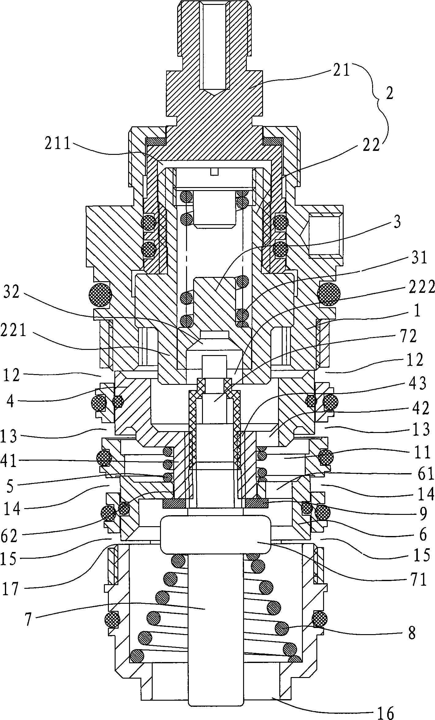
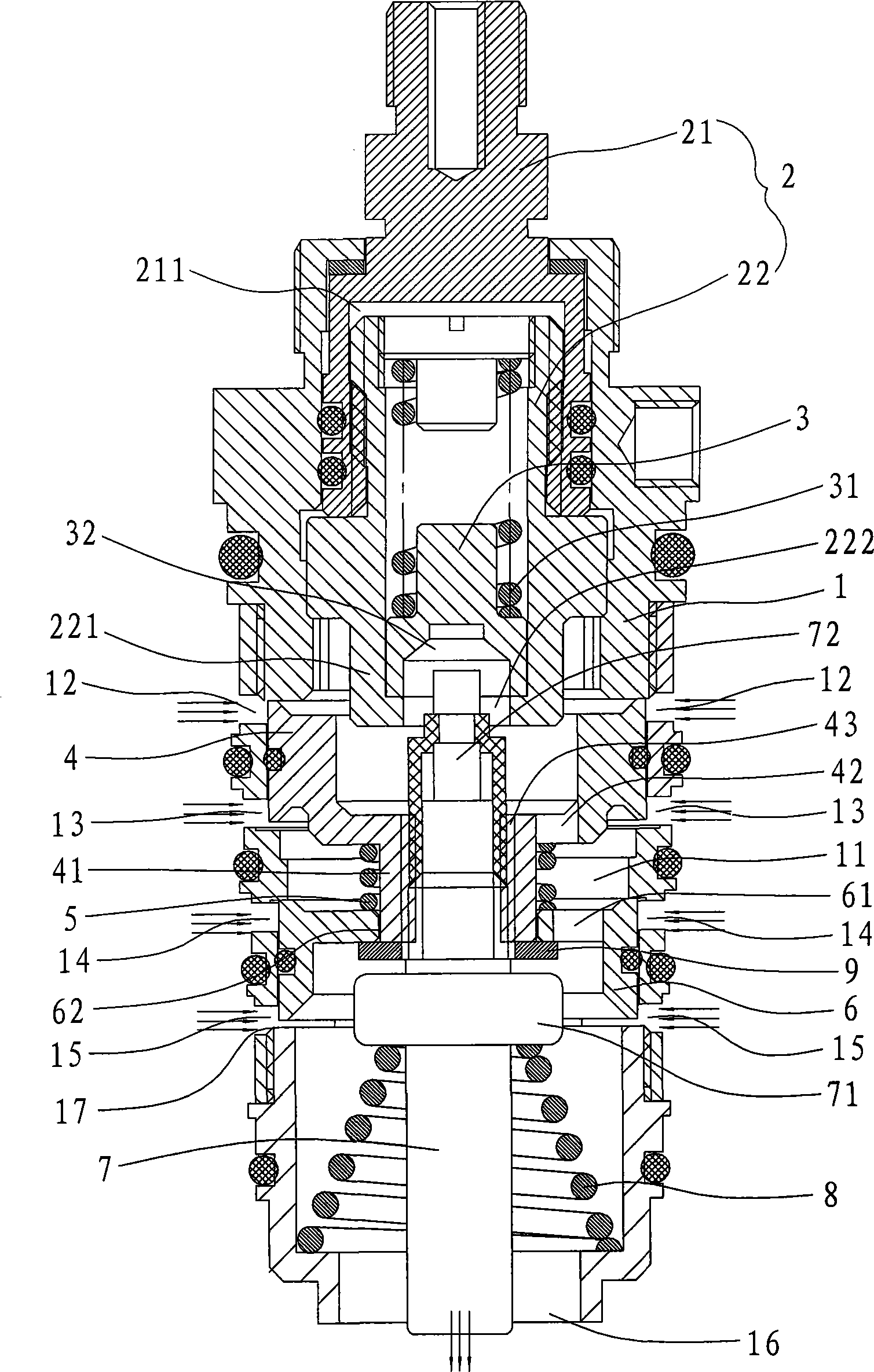
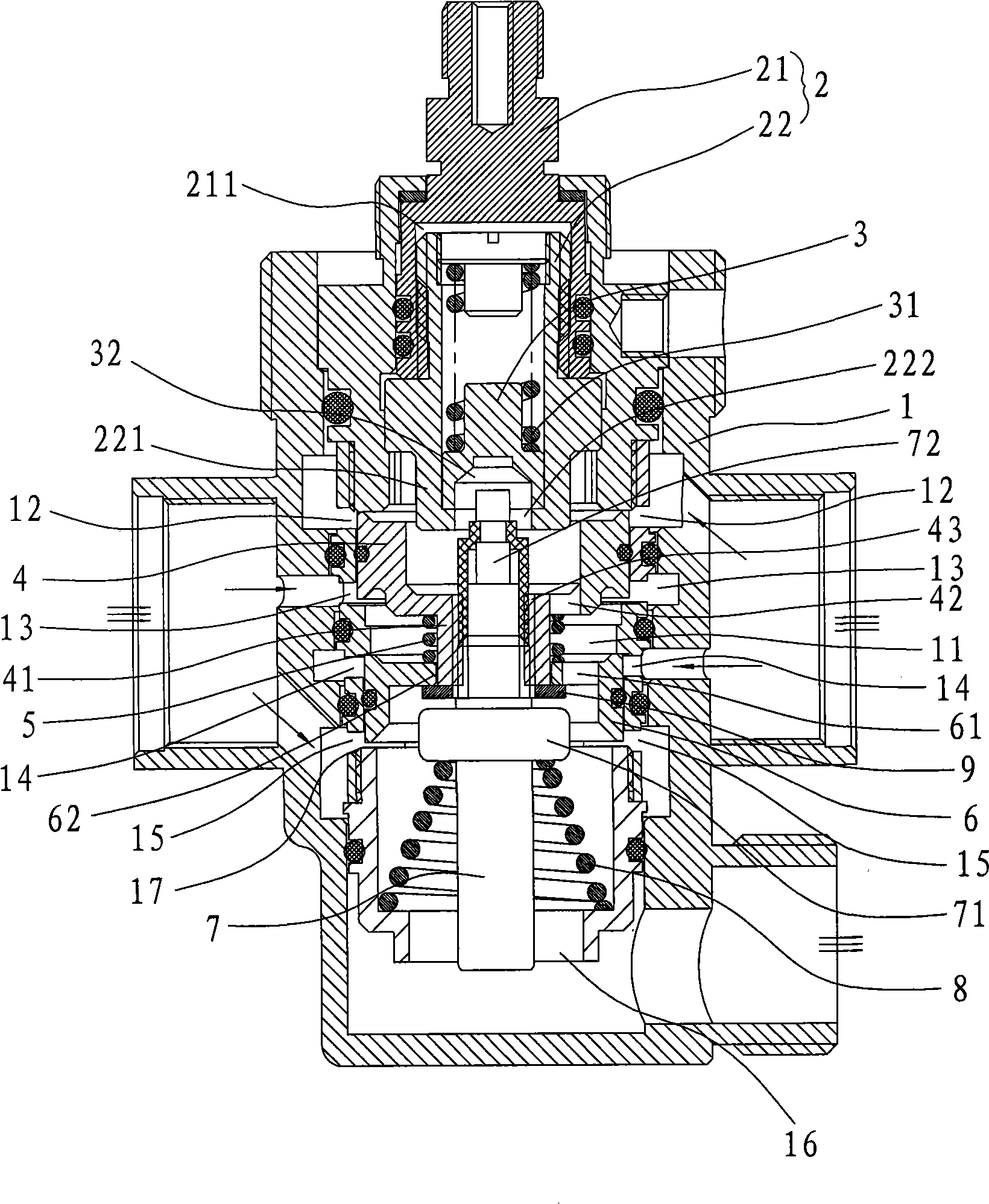
[0020] Such as figure 1 , 2 As shown, a constant temperature control valve provided by the present invention is applied to a hot and cold water supply system, and includes a valve body 1, an adjusting rod 2, a push rod 3, an upper piston 4, a transmission spring 5, a lower piston 6 and a heat sensitive element 7 .

[0021] The valve body 1 is axially formed with a valve cavity 11, and the upper cold water inlet 12 and the upper hot water inlet 13 are arranged on the side wall of the middle part of the valve cavity 11, and the two water inlets are arranged up and down, and on the side wall of the valve cavity 11 The upper hot water inlet 13 below is provided with lower cold water inlet 14 and lower hot water inlet 15 again, and equally two water inlets are arranged up and down; The bottom surface of valve body 1 is provided with outlet 16.

[0022] The adjusting rod 2 includes a rotating rod 21 and a sliding rod 22. The rotating rod 21 is sealed and arranged on the top of the...


PUM


Abstract

A thermostatic control valve comprises a valve body with a cold and hot water inlet and a mixing water outlet, a thermal sensitive element positioned in the valve body and a piston driven by the thermal sensitive element; the piston can adjust the inflow of the cold and hot water inlet; wherein, at least two groups of cold and hot water inlets are arranged from top to bottom of the valve body and at least two pistons controlling the cold and hot water inlets are arranged in the valve body; one of the pistons is fixed with the thermal sensitive element; a driving spring which ensures the distance between adjacent pistons is arranged between pistons. The thermal sensitive element expands or contracts under the condition of change of water outlet temperature, thus driving the pistons to move up and down, increasing or reducing the cold and hot water inlets and adjusting the cold and hot water inflow to facilitate the water outlet temperature to be constant. The cold and hot water inlets are increased on the valve body, thereby realizing the function of big flow; linked by the driving spring, a plurality of pistons can move synchronously under the circumstance of ensuring temperature adjustment. The driving spring has the function of compensating the dimension error so as to improve the safety of effluent of the thermostatic control valve.

Description

technical field [0001] The invention relates to a water outlet temperature control system applied to a hot and cold water supply system, such as a thermostatic valve core, a thermostatic faucet or a constant temperature shower system, in particular to a thermostatic control valve capable of automatically controlling the outlet water temperature and realizing constant temperature water supply. Background technique [0002] When the known water storage type water heater with an open outlet is used, the water in the water storage tank is first heated to a preset temperature, and when using water, the flow rate of the outlet water and the mixing ratio of hot and cold water must be adjusted by hand so that the temperature of the outlet water reaches the water requirement. Along with the prolongation of water use time, the water temperature in the water tank constantly drops, and the mixing ratio of hot and cold water just needs to be constantly adjusted to guarantee that the outle...

Claims


Application Information

Patent Timeline
Patent Type & Authority Applications(China)
IPC IPC(8): F16K11/00F16K31/64
Inventor 彭金兴
Owner XIAMEN SOLEX HIGH TECH IND CO LTD
Why Eureka
Try Eureka