
Rocking arm type die-sinking device

A rocker type, arm body technology, applied in the field of rocker type mold opening devices, can solve the problems of occupation, unfavorable effective use of effective plant area, large space, etc.

Inactive Publication Date: 2009-08-26
陈法胜
View PDF2 Cites 1 Cited by
  • Summary
  • Abstract
  • Description
  • Claims
  • Application Information

AI Technical Summary

Problems solved by technology

[0003] The above-mentioned known technology, specifically as disclosed in the Chinese Taiwan No. 86218106 new patent, is characterized in that the two sides of the machine in the ejection direction are respectively equipped with horizontal arcs to vertical arcs at appropriate positions on the machine table in the ejection direction. The type of track, so that when the upper and lower molds are moved out at the same time, the rollers set on the lift plate can be rolled along the guide rails, so that the upper mold and the lift plate can be lifted at the same time to open the mold. This technology requires an independent The guide track is on both sides of the mold release position, which will cause space occupation and affect the smooth operation of personnel
[0004] Furthermore, the Chinese Taiwan No. 80215148 new patent document discloses that the hook mechanism is fastened to the top mold of the shoe mold moving in the direction of the mold release, so that the top mold is gradually pulled apart during the movement of the shoe mold. , and then the top mold is opened to achieve the purpose of mold opening. These conventional technologies can only enable the top mold to be opened along an arc-shaped trajectory. Compared with the conventional technology disclosed above, it occupies a larger space, and It is not conducive to the effective utilization of the effective plant area

Method used


Image

  • Rocking arm type die-sinking device
  • Rocking arm type die-sinking device
  • Rocking arm type die-sinking device

Examples


Embodiment Construction

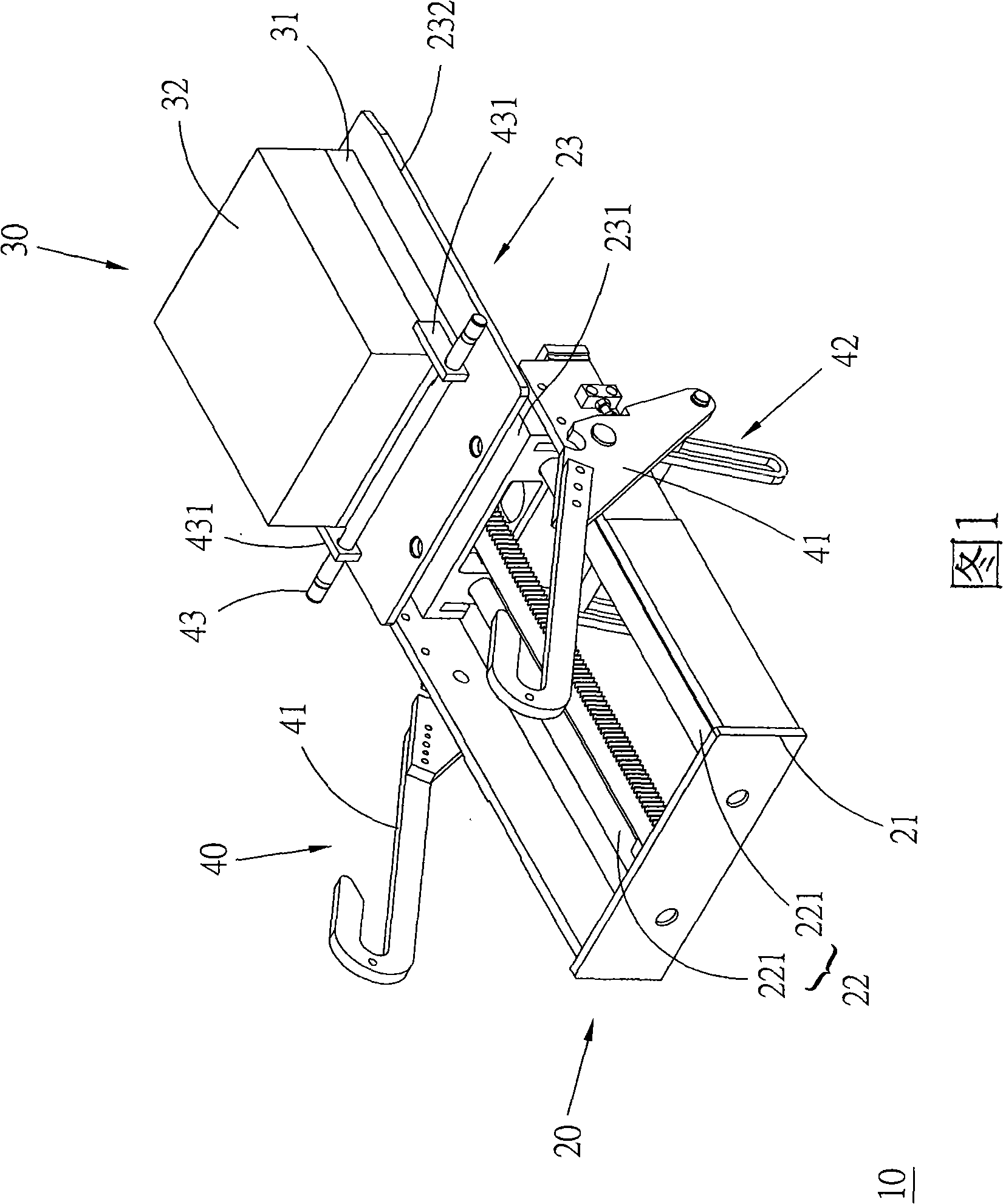
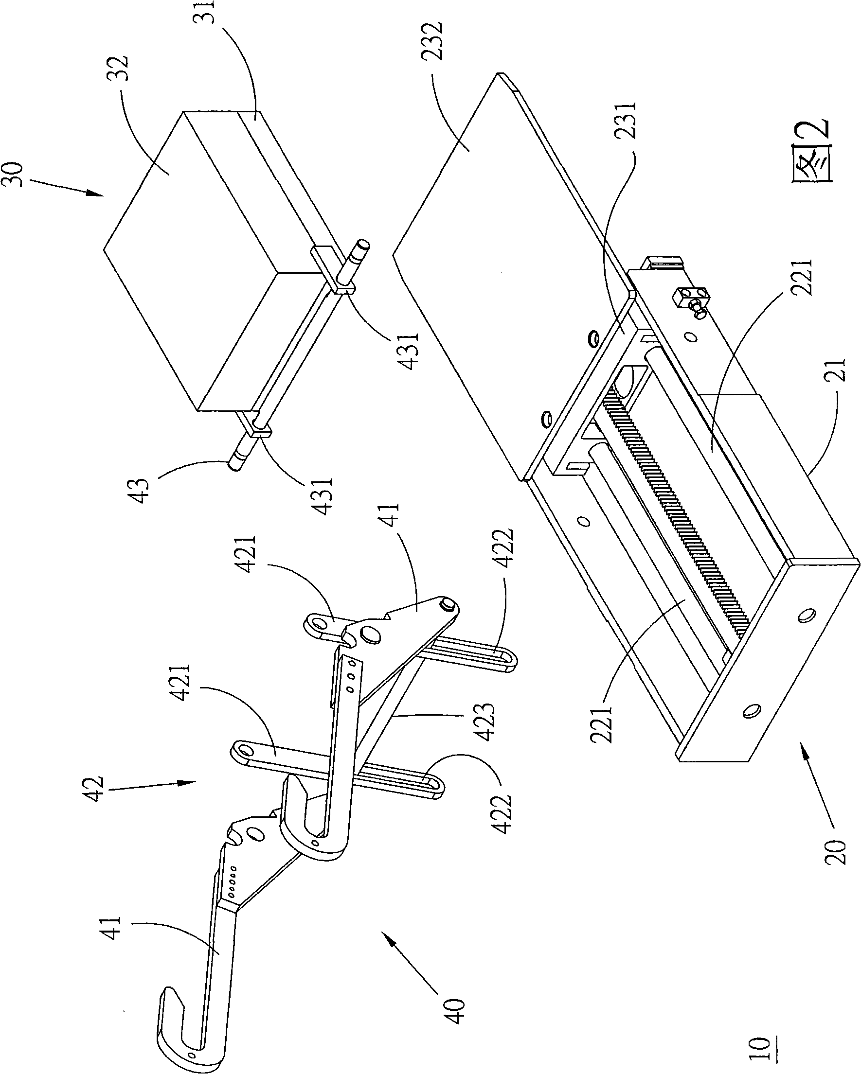
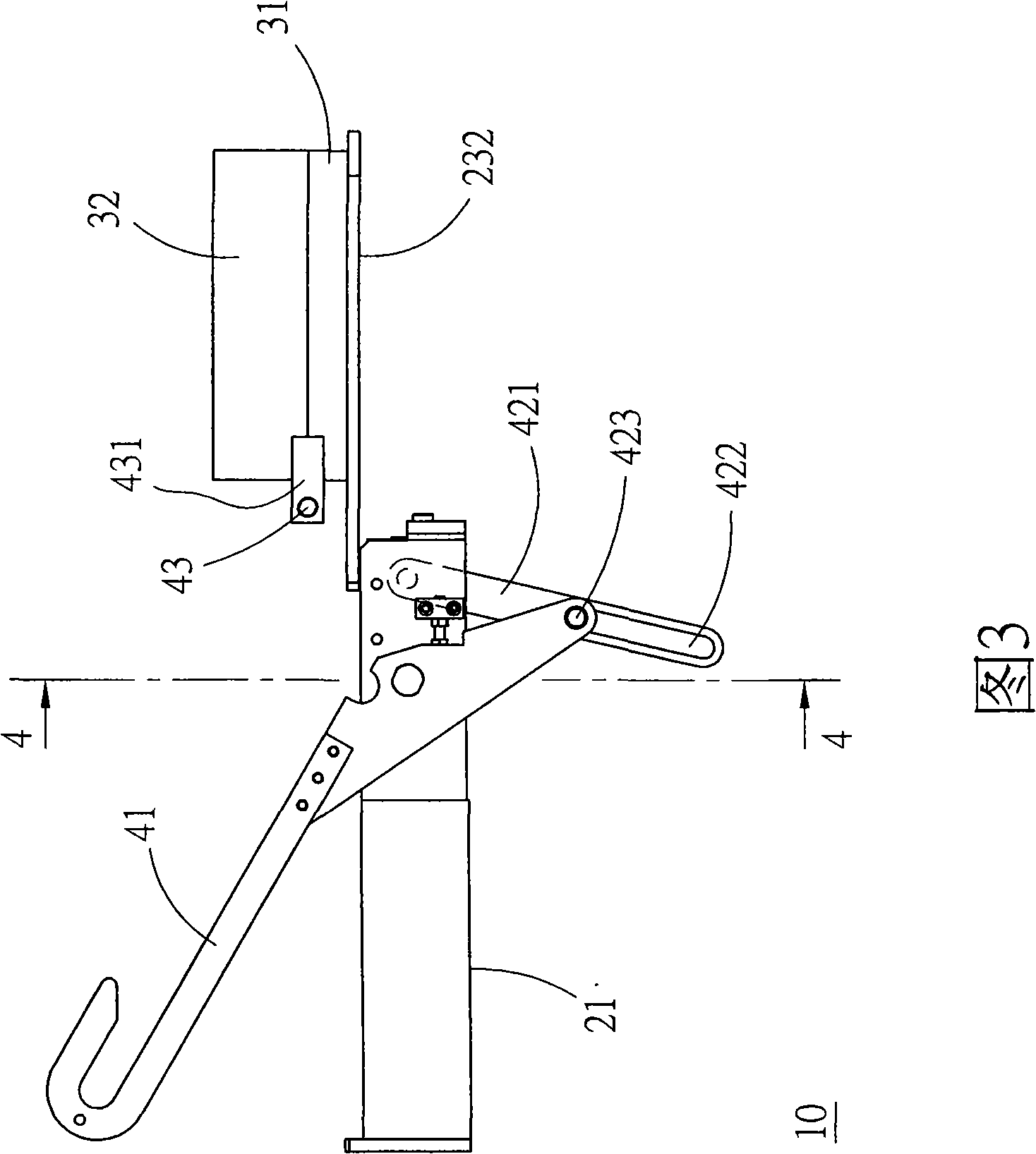
[0014] Please refer to the drawings, the swing arm type mold opening device 10 provided in a preferred embodiment of the present invention is mainly composed of a base 20 , a mold base set 30 and a rocker arm set 40 .

[0015] The base 20 has a rectangular frame-shaped seat body 21, a guide portion 22 composed of two guide rods 221 is parallel to the long axis of the seat body 21 and bridged between the inner facing frame surfaces of the seat body 21 with two ends, A moving part 23 is slidably arranged on the guide part 22, and can reciprocate and linearly displace between a seating position and a seating position along the rod axis direction of the guiding part 22; further, the moving part 23 has a moving block 231, threaded and slidably arranged on each of the guide rods 221, and a seat plate 232 is fixedly connected on the moving block 231 with one end.

[0016] The mold base group 30 has a bottom mold base 31 attached to the base plate 232, a movable mold base 32 is locate...


PUM


Abstract

The invention relates to a rocking arm type die-sinking device, which comprises a base, a die holder set and a rocking arm set, wherein the base is provided with a guiding part and a moving part which is arranged on the guiding part in a sliding mode and is guided by the guiding part to perform reciprocating linear displacement between the positions of an inlet seat and an outlet seat; the die holder set is arranged on the moving part, can perform reciprocating displacement between the positions of the inlet seat and the outlet seat along with the movement of the moving part, and is provided with a movable die holder which can be pivoted between the positions of a closed die and an open die along a direction vertical to the displacement of the moving part; and the rocking arm set is provided with at least one rocking arm with a preset length and is pivoted on the base, a pivot of the rocking arm is parallel with and corresponding to the pivot around which the movable die holder rotates, and the rocking arm set is provided with a connected moving part which is connected between the rocking arm and the moving part, and a connecting piece which is arranged on the movable die holder for connecting the rocking arm; thus, when the moving part moves from the inlet seat to the outlet seat, the connected moving part pivots the rocking arm so as to drive the movable die holder to be lifted and turned from the closed die to the open die through the connecting piece.

Description

technical field [0001] The invention relates to polymer molding processing technology, in particular to a rocker-arm type mold opening device. Background technique [0002] In the polymer molding processing technology, in order to carry out the opening procedure of the multi-layer mold, the conventional technology uses the horizontal displacement of the mold from the mold clamping mechanism as the power source, and cooperates with the appropriate guiding technology content. The specific mold in the mold, usually the upper mold, is pulled up to achieve the expected mold opening. [0003] The above-mentioned known technology, specifically as disclosed in the Chinese Taiwan No. 86218106 new patent, is characterized in that the two sides of the machine in the ejection direction are respectively equipped with horizontal arcs to vertical arcs at appropriate positions on the machine table in the ejection direction. The type of track, so that when the upper and lower molds are move...

Claims


Application Information

Patent Timeline
IPC IPC(8): B29C33/20B29C33/26
Inventor 陈法胜
Owner 陈法胜
Learn More