Combined type variable-pressure exhaust passage structure

An exhaust duct and combined technology, applied in the direction of vertical pipes, building components, building structures, etc., can solve the problems of unfavorable mass production, inconvenient use, inconvenience, etc., and achieve easy use and transportation, easy standardization, and improved stability sexual effect

Inactive Publication Date: 2009-08-26
林润泉
View PDF1 Cites 2 Cited by
  • Summary
  • Abstract
  • Description
  • Claims
  • Application Information

AI Technical Summary

Problems solved by technology

Since the above-mentioned variable pressure component and the intake guide pipe adopt a structure fixed in the exhaust pipe, it is necessary to fix the pressure transformation component and the intake guide pipe in the exhaust pipe first when making the exhaust pipe, which is It makes the manufacturing process more complicated. Once the fixed position is determined, it is impossible to adjust the setting position of the transformer component and the intake guide pipe according to the needs of the user, which is inconvenient to use.
[0003] Chinese utility model patent CN2612758Y discloses a variable-pressure exhaust duct, which is composed of a main pipeline and an auxiliary pipeline. A guide pipe, a pressure-transforming component and a windproof plate are arranged in the secondary pipeline. The plates are pre-fixed in it when making the exhaust duct. If its setting position is suitable for the low-position exhaust gas demand of the bottom exhaust type range hood or exhaust fan, but the user adopts the upper exhaust type range hood or When the fan is exhausted, the setting positions of the guide pipe and the transformer part cannot be adjusted upwards, and the exhaust pipe can only be connected upwards to the air inlet of the exhaust pipe, which is very inconvenient to use and consumes too much of the exhaust pipe. The process is complicated, and it is inconvenient to transport components such as pressure transformers and exhaust pipes as a whole
Therefore, its disadvantages are that it is inconvenient to use and transport, and the manufacturing process is relatively complicated, which is not conducive to mass production.

Method used


Image

  • Combined type variable-pressure exhaust passage structure
  • Combined type variable-pressure exhaust passage structure
  • Combined type variable-pressure exhaust passage structure

Examples


Embodiment 1

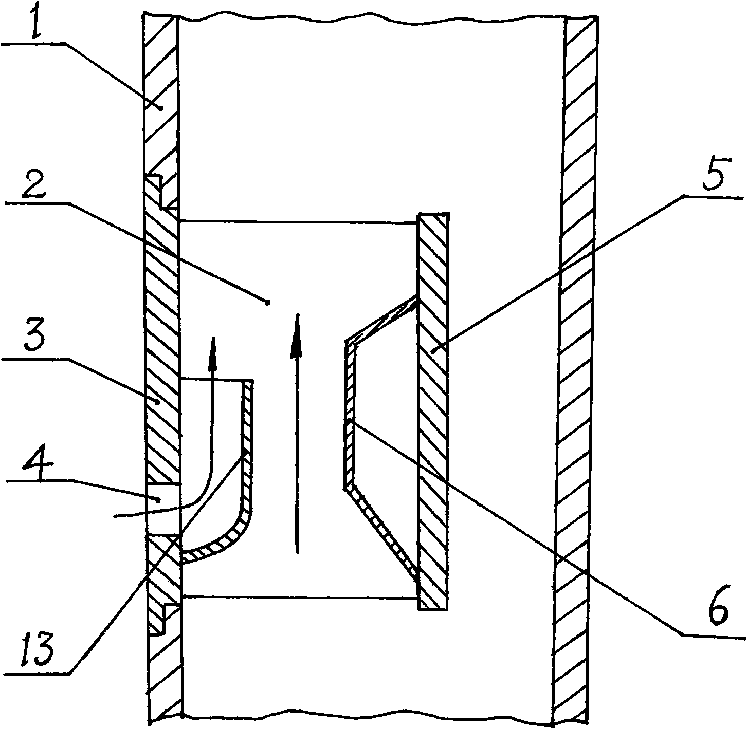
[0022] Example 1, in figure 1 In the structural schematic diagram shown, the present invention includes an exhaust pipe 1 and an airflow pressure changing part arranged on the exhaust pipe 1 and protruding into its inner cavity, wherein the airflow pressure changing part is reduced by narrowing its guide passage The air flow conduction cross-sectional area is used to change the air flow velocity, and the air inlet 4 is arranged on the outer assembly plate 3 of the air flow pressure transformation component, and the air flow pressure transformation component is assembled on the exhaust air flow through its outer assembly plate 3. On the gas pipeline 1, the two constitute a combined assembly structure. exist figure 1 Among them, the airflow pressure conversion component includes an outer assembly plate 3, an inner partition plate 5 and a connecting piece connecting the two as a whole, and it also includes an air intake guide pipe 13 arranged on the inner wall of the outer assem...

Embodiment 2

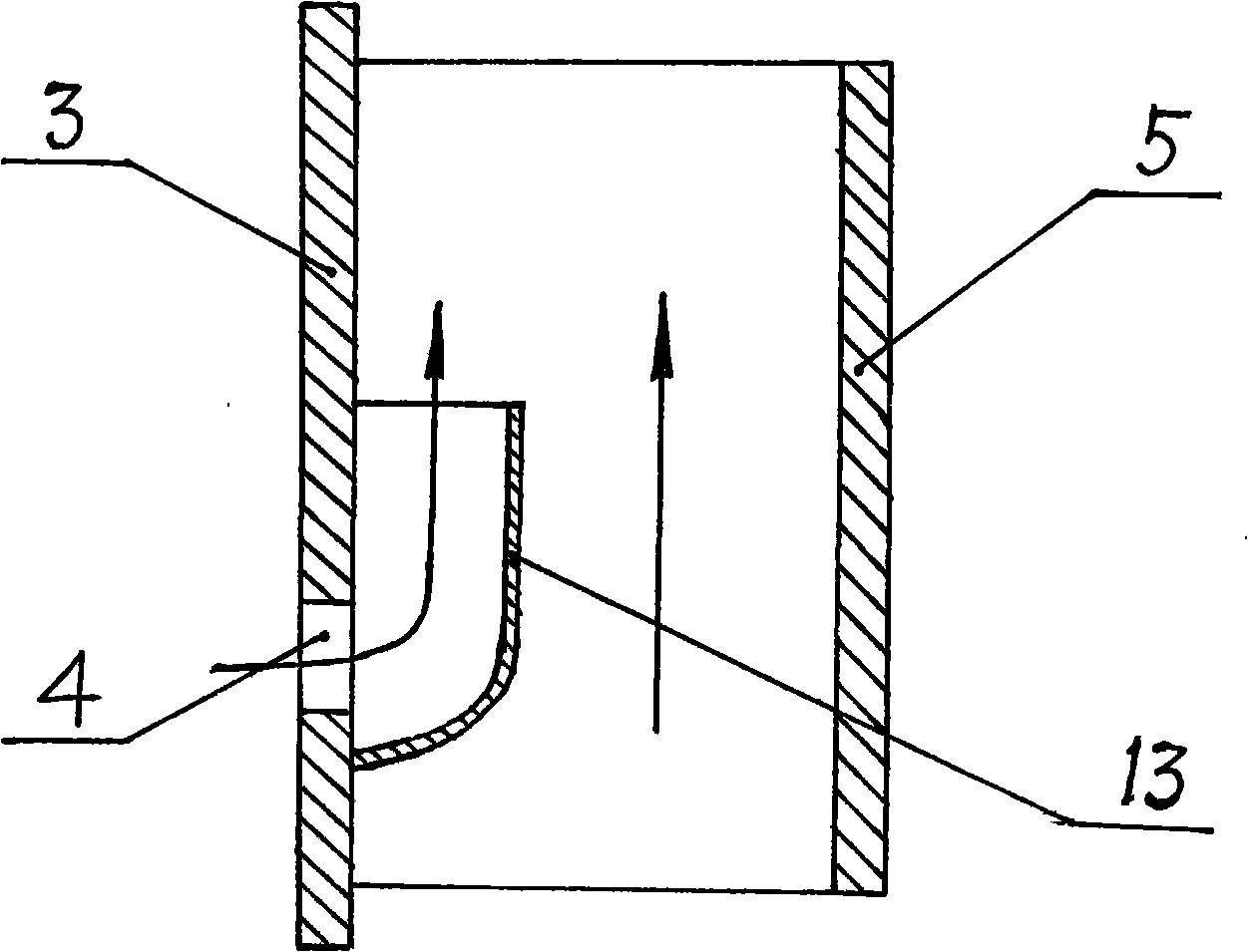
[0023] In Embodiment 2, the present invention has the same structure as that in Embodiment 1 except that the pressure-transforming protrusion is omitted. exist figure 2In the schematic diagram shown, the airflow pressure conversion part of the present invention includes an outer mounting plate 3, an inner partition plate 5 and a connecting piece connecting the two as a whole, and it also includes an air inlet arranged at the inner wall of the outer mounting plate 3. The guide pipe 13 , the air inlet of the air inlet guide pipe 13 and the air inlet 4 provided on the outer assembly plate 3 are butted and communicated with each other. The arrangement of the air intake guide pipe 13 reduces the cross-sectional area of ​​the guide channel of the airflow pressure transformation component, thereby changing the flow rate of the airflow in the channel.

Embodiment 3

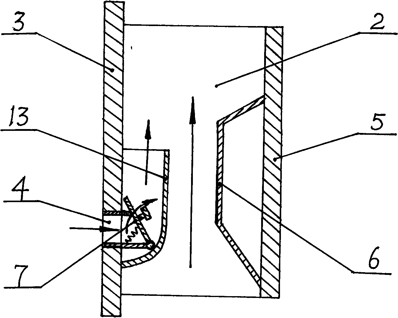
[0024] In Embodiment 3, the present invention has the same structure as that in Embodiment 1 except that a one-way exhaust valve is added. exist image 3 In the schematic diagram shown in the structure, the airflow pressure conversion part of the present invention includes an outer assembly plate 3, an inner partition plate 5 and a connecting piece connecting the two as a whole. The above-mentioned connecting piece is two connecting plane plates, and the connecting plane plate 2 is one of them. In addition, the air flow pressure changing component of the present invention also includes an air intake guide pipe 13 arranged on the inner wall of the outer mounting plate 3, a pressure changing protrusion 6 arranged on the inner wall of the inner partition 5, and a top when the air is inhaled. The one-way exhaust valve 7 that is automatically closed when it is open or does not take in air, the intake pipe mouth of the air intake guide pipe 13 is connected to the air inlet 4, and t...


PUM


Abstract

The invention relates to a combined type variable-pressure exhaust passage structure, which mainly comprises an exhausting pipeline (1) and an airflow variable-pressure component which is assembled on the exhausting pipeline in a combined mode and protrudes in a cavity of the exhausting pipeline, wherein the airflow variable-pressure component changes the airflow speed by reducing the airflow conducting section area in a flow guidance passage thereof so as to achieve effects of preventing taints of smoke and odor. The combined type variable-pressure exhaust passage structure solves the problems that the variable-pressure component in the proposal of the prior art needs to be prearranged fixedly in the exhausting pipeline so that the manufacture, the transportation and the use are inconvenient; besides, the combined type variable-pressure exhaust passage structure has the advantages of easy manufacture, convenient transportation and practical use, and is mainly used for manufacturing variable-pressure flue gas exhausting pipelines for various storied buildings particularly for residential storied buildings for preventing the taints of smoke and odor among floors.

Description

technical field [0001] The invention relates to a component used in a building, in particular to a combined pressure-variable exhaust duct structure used to prevent smoke and smell from passing through each floor of various buildings, especially residential buildings. Background technique [0002] At present, the anti-smog and anti-odor variable pressure exhaust ducts commonly used in buildings and residential buildings are mostly composed of exhaust pipes, variable pressure components fixed in their inner chambers, and intake guide pipes. The component is a component that protrudes into the inner chamber of the exhaust pipe and is arranged opposite to the air intake guide pipe. Since the above-mentioned variable pressure component and the intake guide pipe adopt a structure fixed in the exhaust pipe, it is necessary to fix the pressure transformation component and the intake guide pipe in the exhaust pipe first when making the exhaust pipe, which is This makes the manufact...

Claims


Application Information

Patent Timeline
Patent Type & Authority Applications(China)
IPC IPC(8): E04F17/02
Inventor 林润泉
Owner 林润泉
Why Eureka
Try Eureka