
Emitting device and method for multi-antenna system

A multi-antenna system, the same technology, used in transmission systems, digital transmission systems, baseband system components and other directions

Inactive Publication Date: 2009-08-26
ZTE CORP
View PDF4 Cites 7 Cited by
  • Summary
  • Abstract
  • Description
  • Claims
  • Application Information

AI Technical Summary

Problems solved by technology

But this method is not a very good method, because the adaptive coding and modulation of each layer requires more overhead for information feedback, and this method does not allow the data on each codeword stream to obtain sufficient diversity gain

Method used


Image

  • Emitting device and method for multi-antenna system
  • Emitting device and method for multi-antenna system
  • Emitting device and method for multi-antenna system

Examples


Embodiment 1

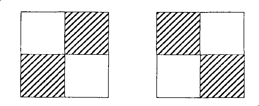
[0085] The following conditions are met when the generated 2 codeword streams are mapped to 2, 3 or 4 channel layers: when the number of symbols of the 2 input codeword streams is equal, the data of each codeword stream is evenly distributed on each layer, And two adjacent symbols on the same layer come from different original code word streams, and two adjacent symbols on the same column come from different original code word streams;

[0086] The data distribution after mapping is shown in Figure 3. Figure 3a A schematic diagram of the minimum mapping unit when 2 codeword streams are mapped to 2 channel layers, Figure 3b A schematic diagram of the minimum mapping unit when 2 codeword streams are mapped to 3 channel layers, Figure 3c It is a schematic diagram of the minimum mapping unit when 2 codeword streams are mapped to 4 channel layers. The complete pattern after mapping is composed of an integer number of minimum mapping units as shown in the figure; where the dimen...

Embodiment 2

[0137] In asymmetric mapping, due to the type of upper-layer services, there is a scenario when the number of symbols in the two generated codeword streams is different, and the number of symbols in one codeword stream is 2 of the number of symbols in the other codeword stream times (in this embodiment, the number of symbols of the second codeword stream is twice that of the first codeword stream), the following methods can be used to map the two codeword streams to three channel layers. This mapping method It has application value in some application scenarios, such as the coexistence of data services with a large amount of data and VOIP services.

[0138] Such as Figure 5a to Figure 5f Shown is a schematic diagram of the minimum mapping unit after mapping. The complete pattern after mapping is composed of an integer number of minimum mapping units as shown in the figure. Each minimum mapping unit includes 3 layers and 3 columns, and each layer contains only one original 1st...


PUM


Abstract

The invention provides an emitting device and method for a multi-antenna system. The method includes that data to be transmitted is generated to two code word flow and is mapped to a channel layer by a transmitting terminal, the mapped data is conversed, treated by pre-coding and transmitted; when symbol number of the two code word flow is same, in the mapped data, adjacent two symbols in each layer are from different code word flows, and adjacent two symbols in each column are from different code word flows. The present invention can make the data of each code word flow acquire full diversity gain, and greatly increase performance of space multiplexing, in addition, due to employing dynamic mapping mode, the invention can flexibly select mapping mode according to transmission performance information of each channel layer and increase transmission rate and transmission reliability.

Description

technical field [0001] The present invention relates to the communication field, in particular to a transmitting device and method for a multi-antenna system. Background technique [0002] In wireless communication, if multiple antennas are used at both the sending end and the receiving end, we can adopt a spatial multiplexing method to obtain a higher rate, that is, transmit different antennas at different antenna positions on the same time-frequency resource at the transmitting end. Data, since each channel can be estimated by channel estimation at the receiving end, even if each antenna transmits different data, after passing through the multiple transmission and multiple reception (MIMO) signal matrix, the transmission data on each antenna can still be solved at the receiving end. [0003] Compared with the method of directly solving the data transmitted on each antenna by using the signal matrix, an enhanced means is to use the precoding technology. At the transmitting...

Claims


Application Information

Patent Timeline
IPC IPC(8): H04L1/06H04L1/00H04L25/03
Inventor 陈艺戬戴博郁光辉罗宇民
Owner ZTE CORP
Learn More