Water collection system

A technology of water collection and water tank, applied in the field of water collection system

Inactive Publication Date: 2009-08-26
RAINMAX
View PDF0 Cites 12 Cited by
  • Summary
  • Abstract
  • Description
  • Claims
  • Application Information

AI Technical Summary

Problems solved by technology

The rainwater storage tank is usually only connected to one or two bypass pipes, so only a part of the rainwater falling on the entire roof can be captured

Method used


Image

  • Water collection system
  • Water collection system
  • Water collection system

Examples


Embodiment Construction

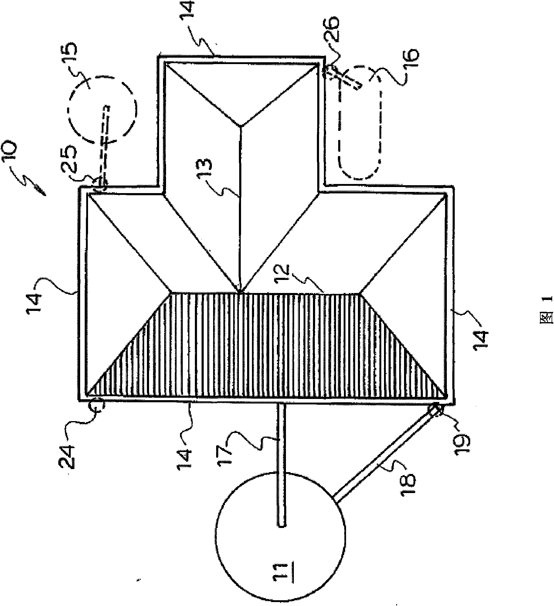
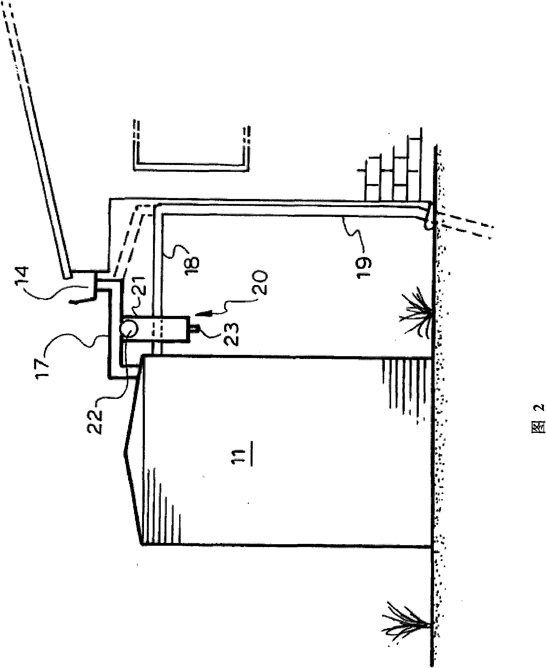
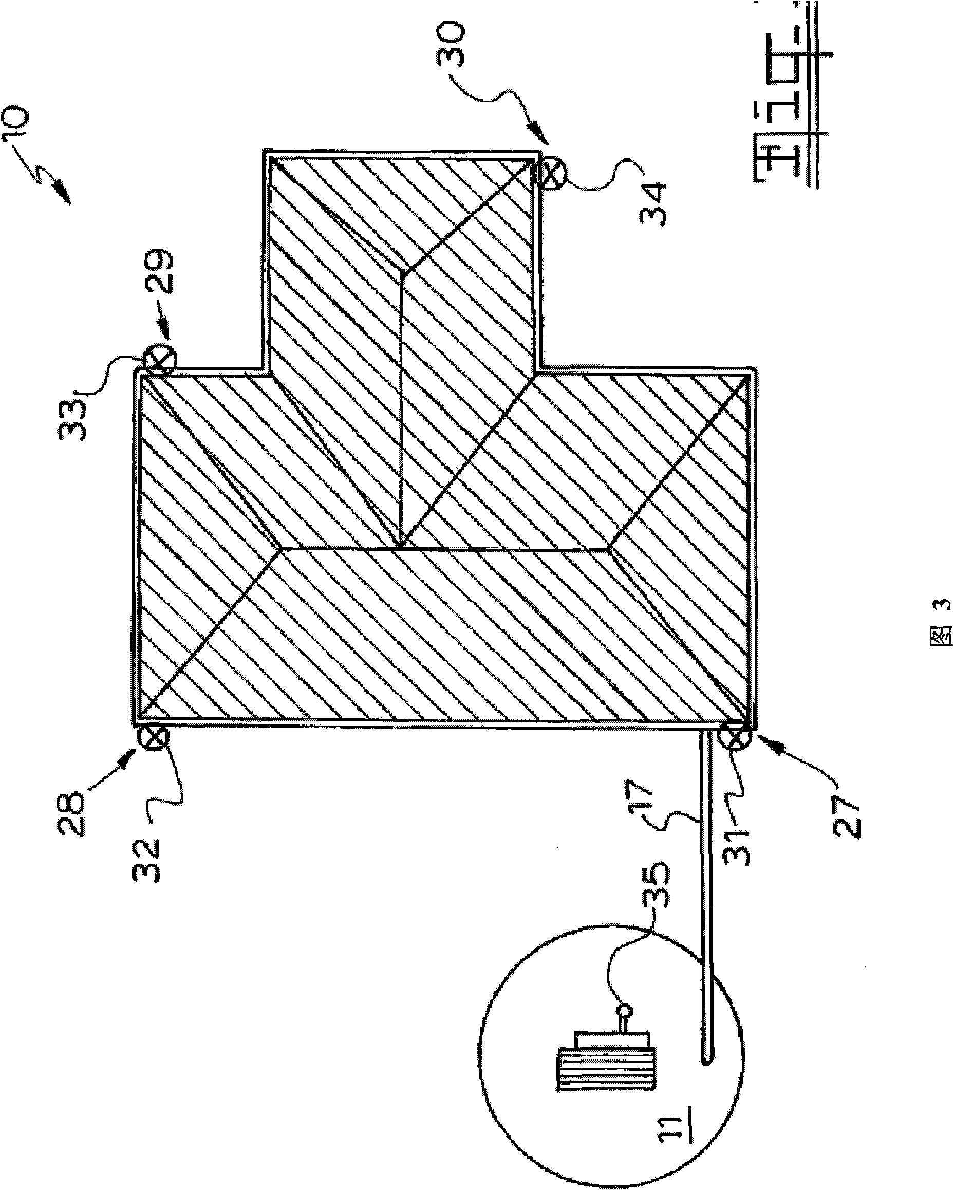
[0042] Referring to the accompanying drawings, the first is figure 1 , which illustrates a prior art arrangement where the roof 10 of a dwelling has a water tank placed at 11. In this case the roof is T-shaped with ridges 12 and 13 and when it rains the water flows to the surrounding gutters 14 . To collect all the water, additional tanks are required in this case for a total of three tanks. The tank can be located at 11 or at 15 or 16 in the model in the figure in order to take advantage of the whole roof catchment, but with the tank 11 the rainwater falling on the shaded area 12 of the roof will be all that is collected in the storage tank. All water in the water tank 11. The rest of the roof shown does not collect rainwater beyond this area, so that rainwater will easily become fall rain. This is due to the required drop on each part of the flume, which must have an apex. Water flows to the water tank 11 through the connecting pipe 17, while the overflow pipe of the wat...


PUM


Abstract

The present invention relates to a water collection system, which blocks down-pipes to collect water from a roof. A down-pipe (27) is located adjacent a rain water diversion unit (31). The unit comprises a box (36) with the down-pipe (27) fitted to an opening (37) in bottom (38) of the box (36). The gutter (14) has two side-by-side openings (39 and 40), the opening (40) has an overflow in the form of upstanding wall (41) while the opening (39) has a valve plate (42) hinged to the front edge at (43). A pneumatic actuator (44) is used to move the valve plate (42) to the closed position. When the valve is closed, the opening (40) and the upstanding wall (41) serve as an overflow back to the stormwater via the box (36). The tank pipe (17) also has an opening (45) with an upstanding wall (46) which has its upper edge (47) set lower than the upper edge (48) of the wall (41) of the overflow. All down-pipes are fitted with diversion units. A controller includes a rain sensor to detect a rain event whereupon a time delay is imposed for first flush to flush the roof before the valves close the down-pipes. When the tank is full a float is used to operate the controller to open the valves if they are closed or prevent them closing in the case of a new rain event and the tank being already full.

Description

technical field [0001] The present invention relates to a water collection system, particularly but not limited to a water collection system for collecting rainwater from the roof of a dwelling or house. Background technique [0002] Currently, rainwater is usually collected from only parts of the roof, and this collected rainwater is then conveyed into a rainwater storage tank. The rainwater storage tank is usually only connected to one or two bypass pipes, so that only a part of the rainwater falling on the entire roof can be captured. This means that only part of the rainwater is received. [0003] It is an object of the present invention to utilize more roofs to recover a greater proportion of the precipitation that falls on any particular roof. The invention can be adapted to new building configurations or retrofitted to existing buildings with only minor changes. [0004] It is therefore an object of the present invention to use existing roof guttering in a preferre...

Claims


Application Information

Patent Timeline
Patent Type & Authority Applications(China)
IPC IPC(8): E04D13/04E03B3/02
CPCE04D13/0645E03B3/02E04D2013/0853E04D13/08Y02A20/108
Inventor 马克·布伦丹·弗拉纳根
Owner RAINMAX
Why Eureka
Try Eureka