Supercharge Your Innovation With Domain-Expert AI Agents!

Method and apparatus for fast channel change for digital video

A channel and video streaming technology, applied in the field of digital video, can solve problems such as complex middleware support

Inactive Publication Date: 2009-08-26
THOMSON RES FUNDING
View PDF0 Cites 4 Cited by
  • Summary
  • Abstract
  • Description
  • Claims
  • Application Information

AI Technical Summary

Problems solved by technology

[0010] The disadvantage of such systems is that they require complex middleware support

Method used


Image

  • Method and apparatus for fast channel change for digital video
  • Method and apparatus for fast channel change for digital video
  • Method and apparatus for fast channel change for digital video

Examples


no. 1 example

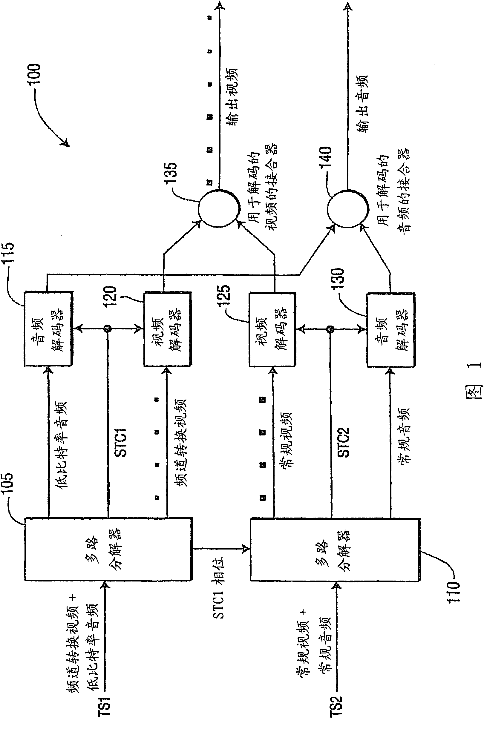
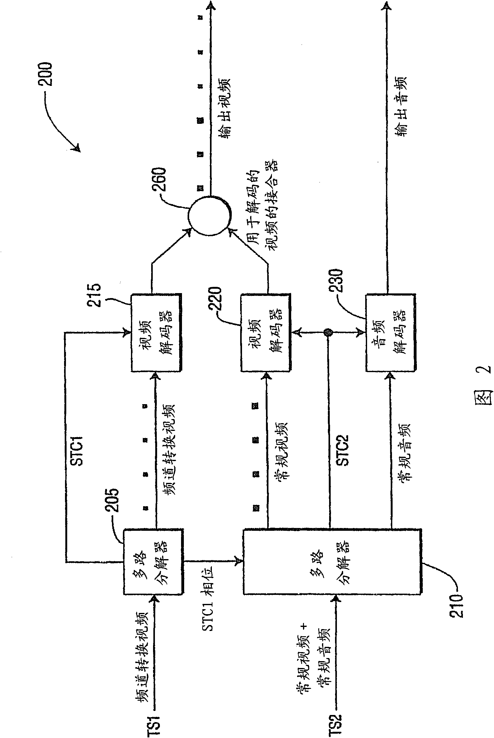
[0068] For the first embodiment, the audio stream associated with the zapping video stream is first decoded and played. The decoder then switches to the audio stream associated with the regular video stream. For the second embodiment, during and after a channel change, the audio stream associated with the regular video stream is decoded and played.

[0069] For the first embodiment and the second embodiment, since the transfer delays of the two streams are different, their system clocks have a phase shift after clock recovery. A phase compensation unit may be employed with respect to at least one of the two streams to eliminate the phase difference of the two system clocks before they are fed to the decoder.

[0070] go to Figure 4 , an exemplary clock synchronization system for synchronizing clock values ​​between two transport streams carrying regular and zapping video streams, respectively, is indicated generally by reference numeral 400. The clock synchronization syste...


PUM


Abstract

There are provided methods and apparatus for fast channel change for digital video. An apparatus includes at least one encoder (805, 810) for receiving normal video data and channel change video data and encoding the normal video data and the channel change video data in a normal video stream and a channel change video stream, respectively, using a common system clock to provide synchronization between the normal video stream and the channel change video stream. The normal video stream and the channel change video stream are encoded for transport separately at a transport level.

Description

[0001] Government Licensing Rights in Federally Sponsored Research and Development [0002] The US Government has a paid license and limited right in this invention to require the patentee to license others on reasonable terms provided under the terms of Project ID Contract No. 2003005676B awarded by the National Institute of Standards and Technology. [0003] Cross References to Related Applications [0004] This application claims the benefit of US Provisional Application Serial No. 60 / 834,308, filed July 28, 2006, the contents of which are hereby incorporated by reference in their entirety. technical field [0005] The present principles relate generally to digital video, and more particularly to methods and apparatus for fast channel changing for digital video. Background technique [0006] Modern video compression techniques are able to achieve a high degree of compression by exploiting the temporal correlation of video frames. In a group of pictures (GOP), only one p...

Claims


Application Information

Patent Timeline
IPC IPC(8): H04N7/24
CPCH04N21/434H04N21/4384H04N21/2365H04N21/4307H04N21/4347H04N21/4383H04N21/2662H04N21/4305H04N21/44016H04N21/23424H04N21/43072H04N5/50H04N21/44
Inventor 阿兰·J·斯坦戴季望约翰·Q·李卢秀萍
Owner THOMSON RES FUNDING
Features
  • R&D
  • Intellectual Property
  • Life Sciences
  • Materials
  • Tech Scout
  • Unparalleled Data Quality
  • Higher Quality Content
  • 60% Fewer Hallucinations
Learn More