Device for measuring positioning force of magnetoelectric linear motor

A permanent magnet linear motor and measuring device technology, applied in the direction of measuring device, measuring force, instrument, etc., can solve the problems of low measurement accuracy, many human factors, uncontrollable measurement process, etc., and achieves high test accuracy, low cost, structure simple effect

CN101520348AInactive Publication Date: 2009-09-02HARBIN INST OF TECH
0 Cites 11 Cited by

Patent Information

Authority / Receiving Office
CN · China
Patent Type
Applications(China)
Current Assignee / Owner
Publication Date
2009-09-02
Estimated Expiration
Not applicable · inactive patent

Smart Images

  • Figure 1
    Figure 1
  • Figure 2
    Figure 2
  • Figure 3
    Figure 3
Patent Text Reader

Abstract

The invention relates to a device for measuring the positioning force of a magnetoelectric linear motor, belonging to the field of motor test and aiming to solve the problems of low measuring precision, a plurality of personal measurement factors and uncontrollable measurement process of a spring balance which is adopted to measure the positioning force of the magnetoelectric linear motor. The device for measuring the positioning force of the magnetoelectric linear motor adopts two synchronizing wheels, a synchronizing belt, a magnetoelectric linear motor mover and a step motor to form a mechanical-structure closed loop; a miniature step rotation angle of the step motor is converted to the miniature displacement of the magnetoelectric linear motor mover in the horizontal direction; a computer, two tension sensors, the step motor and step motor control form an electric control system closed loop, the computer is utilized to process signals of the two tension sensors to obtain the positioning force of the magnetoelectric linear motor, realize the high-precision equidistant position control and record the displacement and the positioning force of each step to form a whole-course positioning force curve. The invention is mainly used for measuring the positioning force of the magnetoelectric linear motor.
Need to check novelty before this filing date? Find Prior Art

Description

technical field

[0001] The invention relates to a positioning force measuring device of a permanent magnet linear motor, which belongs to the field of motor testing. Background technique

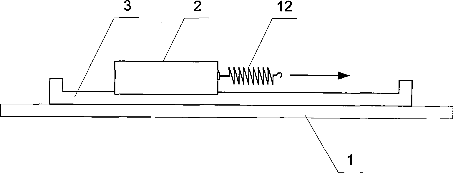
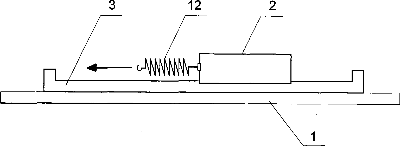
[0002] Linear motor is an extension of traditional motor, which has been valued and recognized by all walks of life. The measurement of the positioning force of the permanent magnet linear motor has always been an indispensable step in the study of the permanent magnet linear motor. The accurate measurement of the positioning force of the permanent magnet linear motor is of great significance to the design and optimization of the permanent magnet linear motor. The existing permanent magnet linear motor positioning force measurement such as figure 1 and figure 2 As shown, the device consists of a test platform 1, a mover 2 of a permanent magnet linear motor, a stator 3 of a permanent magnet linear motor and a spring balance 12. By manually pulling the spring balance 12 to drive the move...

Examples

specific Embodiment approach 1

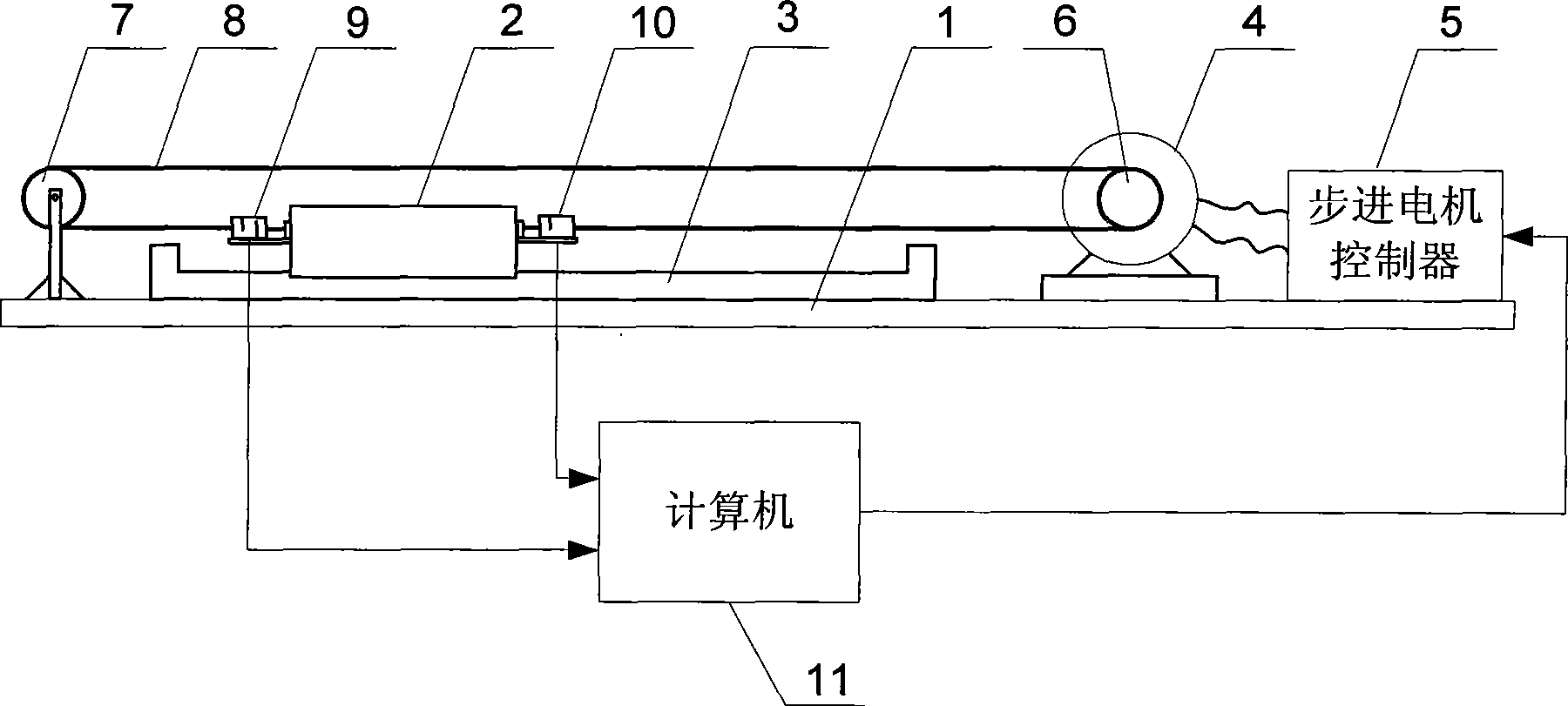
[0011] Specific implementation mode one: the following combination image 3 Describe this embodiment, this embodiment includes test platform 1, permanent magnet linear motor, stepper motor 4, stepper motor controller 5, active synchronous wheel 6, driven synchronous wheel 7, synchronous belt 8, first tension sensor 9 , the second tension sensor 10 and computer 11,

[0012] The permanent magnet linear motor includes a mover 2 and a stator 3. The permanent magnet linear motor is arranged on the test platform 1 and is located between the driving synchronous wheel 6 and the driven synchronous wheel 7. One end of the mover 2 of the permanent magnet linear motor is connected to the first One end of a tension sensor 9 links to each other, the other end of the first tension sensor 9 links to one end of the synchronous belt 8, the other end of the synchronous belt 8 links to one end of the second tension sensor 10, the other end of the second tension sensor 10 is connected to the perma...

specific Embodiment approach 2

[0015] Embodiment 2: The difference between this embodiment and Embodiment 1 is that the diameters of the driving synchronous wheel 6 and the driven synchronous wheel 7 are equal, and other components and connection methods are the same as Embodiment 1.

specific Embodiment approach 3

[0016] Embodiment 3: The difference between this embodiment and Embodiment 1 is that the permanent magnet linear motor is a permanent magnet flat linear motor, a permanent magnet cylindrical linear motor or a permanent magnet bilateral structure linear motor, and other components and connection methods It is the same as Embodiment 1.