Supercharge Your Innovation With Domain-Expert AI Agents!

Display drive system

一种显示器、显示器件的技术,应用在补偿烧屏领域,能够解决显示器总体老化、驱动电压增大、变化等问题

Inactive Publication Date: 2009-09-02
CAMBRIDGE DISPLAY TECH LTD
View PDF11 Cites 4 Cited by
  • Summary
  • Abstract
  • Description
  • Claims
  • Application Information

AI Technical Summary

Problems solved by technology

[0020] One problem associated with OLED displays is that pixels "burn in" over time, i.e. the drive voltage required for a given drive current (and thus luminosity) increases with use
In particular, the luminosity at a given current may drop sharply during the initial drive of an OLED display and then decay to become more uniform
Burn-in thus causes two distinct but related problems: first, the overall aging of the display with use; and second, image burn-in, where continuously displaying one image causes the display pixels to age differently
However, this approach suffers from the disadvantage that the voltage drop across the OLED also varies with temperature and this leads to a brightness change on the display that is proportional to the temperature on the display

Method used


Image

  • Display drive system
  • Display drive system
  • Display drive system

Examples


Embodiment Construction

[0047] refer to Figure 4a and Figure 4b , which respectively show the curves of OLED efficiency (unit: candela / ampere) versus driving time (unit: hour) and OLED driving voltage (unit: volt) versus driving time (unit: hour). These two curves have been fitted by the same extended exponential function:

[0048] exp - ( t τ ) n or 1 - exp - ( t τ ) n

[0049] It can be seen that there is a strong correlation between the drop in OLED device efficiency and the increased drive voltage required for the same drive / light output. The driving voltage V can be expressed as follows:

[0050] V = V 0 = 2 ...


PUM


Abstract

The present invention discloses a display drive system. The invention generally relates to methods, apparatus and computer program code for improved OLED (organic light emitting diode) display drive systems, in particular to compensate for burn-in. A method of compensating an OLED display device for burn-in of pixels of the OLED display, the method comprising: measuring a first voltage drop across at least one test pixel of the display; measuring a second voltage drop across at least one other pixel of the display; determining, from said first and second voltages and a from value (V1) representing a drive voltage increase for a loss in efficiency of said display due to burn-in, an estimated reduction in efficiency of said display due to burn-in; and compensating a drive to said display using said estimated efficiency reduction.

Description

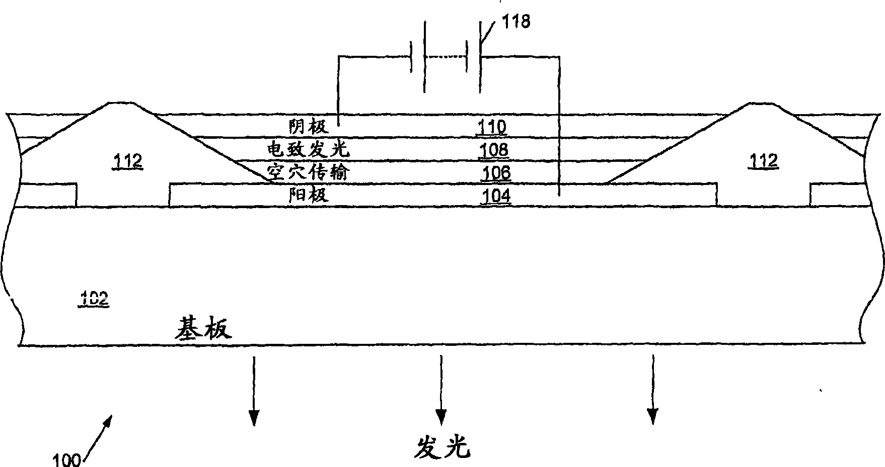
technical field [0001] The present invention relates generally to methods, apparatus and computer program code for improved OLED (Organic Light Emitting Diode) display driving systems, and more particularly to compensating for burn-in. Background technique [0002] Organic light emitting diodes, here including organometallic LEDs, can be fabricated using materials including polymers, small molecules and dendrimers, and can be made in a range of colors depending on the materials used. Examples of polymer-based organic LEDs are described in WO 99 / 21935 and WO 02 / 067343; examples of dendrimer-based materials are described in WO 99 / 21935 and WO 02 / 067343; and so-called based Examples of small molecule devices are described in US 4,539,507. A typical OLED device includes two layers of organic material, one of which is a layer of light-emitting material (e.g., a layer of light-emitting polymer (LEP), oligomer, or light-emitting low-molecular-weight material) and the other layer i...

Claims


Application Information

Patent Timeline
Patent Type & Authority Applications(China)
IPC IPC(8): G09G3/32
CPCG09G2320/045G09G2300/0842G09G2320/043G09G3/3241G09G2320/029G09G3/3233G09G2320/048G09G3/3216G09G3/3208G09G3/20G09G3/30
Inventor E·史密斯
Owner CAMBRIDGE DISPLAY TECH LTD
Features
  • R&D
  • Intellectual Property
  • Life Sciences
  • Materials
  • Tech Scout
  • Unparalleled Data Quality
  • Higher Quality Content
  • 60% Fewer Hallucinations
Learn More