
Bicycle generator

A generator and bicycle technology, applied in bicycle accessories, transportation and packaging, optical signals, etc., can solve the problems of tire wear, inconvenient installation of generators, and failure of bicycle generators to generate electricity normally, so as to improve adaptability, installation and stability. The effect of easy disassembly process

Inactive Publication Date: 2009-09-09
SHANGHAI INST OF TECH
View PDF0 Cites 0 Cited by
  • Summary
  • Abstract
  • Description
  • Claims
  • Application Information

AI Technical Summary

Problems solved by technology

[0004] The present invention aims to solve the technical problem that the bicycle generator cannot generate electricity normally in mud, ice and snow, avoid the technical problem of tire wear caused by long-term use, overcome the problem of inconvenient installation of the original generator, and provide a bicycle with generator

Method used


Image

  • Bicycle generator
  • Bicycle generator
  • Bicycle generator

Examples


Embodiment Construction

[0026] The present invention will be further described below in conjunction with accompanying drawing and embodiment.

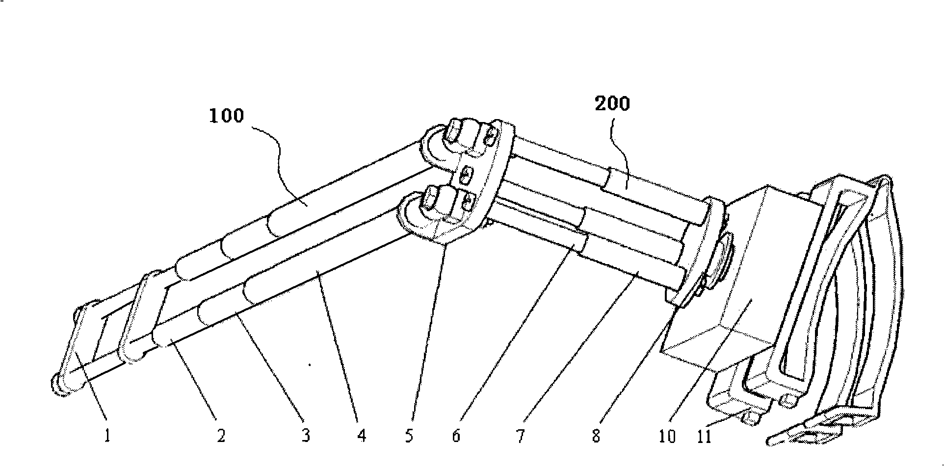
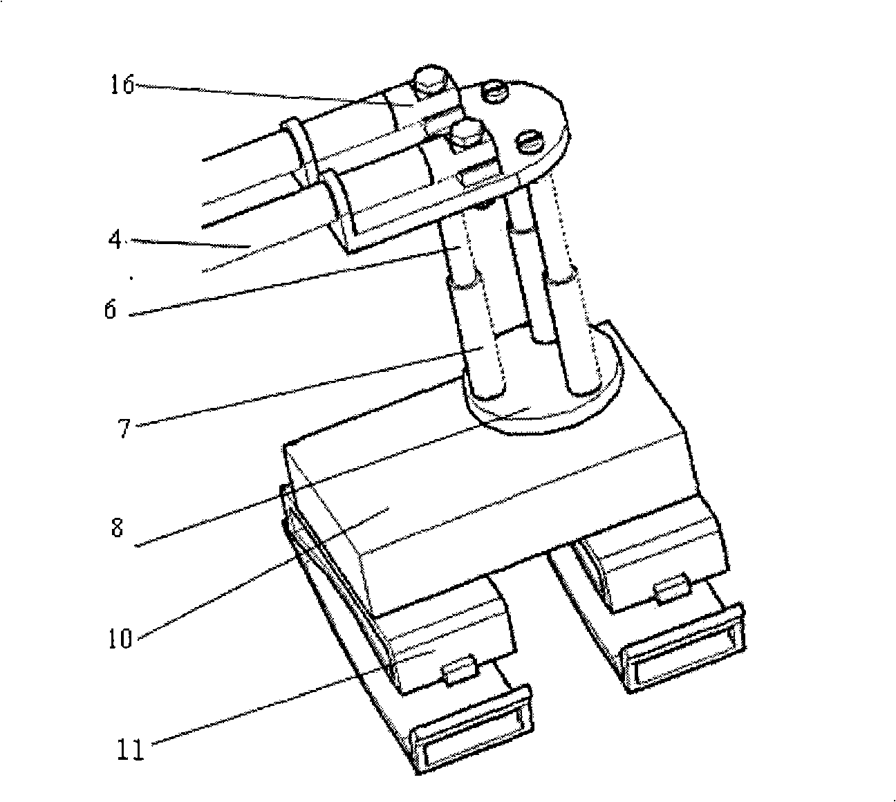
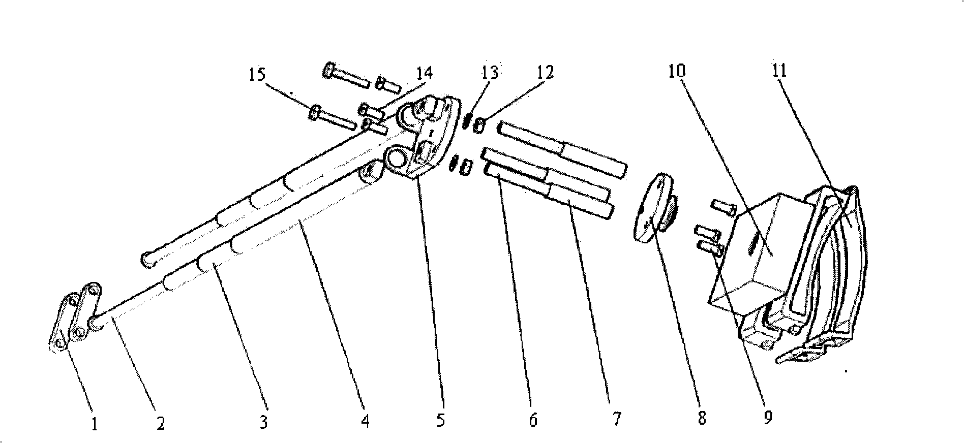
[0027] Such as Figure 1 to Figure 3 As shown, the present invention is made up of rocking bar 100, turntable 200, generator box 10 and fixing device 11. The rocker 100 is made up of a push rod 2 , a sleeve a3 , a sleeve b4 and a swing rod connecting piece 16 . A gap fit is adopted between the ejector rod 2, the sleeve a3 and the sleeve b4, which can produce relative sliding. An interference fit is used to fix the swing link connecting piece 16 and the sleeve b4. After the fork passes through the hole at the front end of the upper platen 5 of the turntable, the fork link 16 is bolted to the upper platen 5 of the turntable. The other end of the fork is tightly connected with two sections of elastic rubber 1 sleeves.

[0028] The turntable 200 is made up of the upper platen 5 of the turntable, the lower platen 8 of the turntable and three connecting rods. ...


PUM


Abstract

The invention relates to a bicycle generator. The generator comprises a rocker, a rotating platform, a generator case and a fixing device. The rocker consists of a post rod, a sleeve a, a sleeve b and a swinging rod connection piece, wherein, the post rod, the sleeve a and the sleeve b are connected in a sliding fit manner, the swinging rod connection piece and the sleeve b are connected in a interference fit manner; the rotating platform consists of an upper bedplate, a lower bedplate and three connection rods, a rear end of the swinging rod passes through a hole in the front end of the upper bedplate and then is fixed with the upper bedplate by the swinging rod connection piece, and the front end of the swinging rod is closely sheathed by two sections of elastic rubber sleeves; and a connecting shaft at a lower end of the lower bedplate passes through a shell of the generator case and is fixedly connected with a connection driving piece, and a pair of arc lugs at the left end of the connection driving piece are inserted into an slot at the right end of a first driving wheel. The generator can avoid problems caused by generating out of tyre friction and can normally generate electricity in the case that tyres become wet and sliding or are stuck with mud in rain or snow as drive of the generator does not rely on the tyres.

Description

technical field [0001] The invention relates to a generator, in particular to a generator used on a bicycle. Background technique [0002] At present, a small wheel is installed on the bicycle fork in the known bicycle dynamo as a transmission member, which is pressed on the tire and rolled. The disadvantage of this type of generator is that when the tires are stuck with mud, or encounter ice and snow, the small wheels often do not rotate, but slide on the tires, so they cannot generate electricity. Moreover, the installation of this type of generator is not convenient enough, and tools are required to tighten the bolts, so it cannot be installed by hand. [0003] When the fasteners of this type of generator on the fork come loose, the generator may get stuck between the spokes, causing an accident. In addition, long-term use of the transmission parts pressed against the tires will damage the tires. Contents of the invention [0004] The present invention aims to solve ...

Claims


Application Information

Patent Timeline
Patent Type & Authority Applications(China)
IPC IPC(8): B62J6/06
Inventor 陈宇侃赵舒涛李光磊钱平
Owner SHANGHAI INST OF TECH
Learn More