Rotary switch

A rotary and switch technology, applied in the direction of electric switches, electrical components, circuits, etc., to achieve the effect of improving safety performance, good conductive channels, and high safety performance

Inactive Publication Date: 2009-09-09
湖州莱檬电子科技有限公司
View PDF1 Cites 16 Cited by
  • Summary
  • Abstract
  • Description
  • Claims
  • Application Information

AI Technical Summary

Problems solved by technology

[0003] The invention provides a rotary switch, which solves the hidden safety problem of creepage caused by the switch being easily dampened in the prior art when the switch is installed in a humid environment

Method used


Image

  • Rotary switch
  • Rotary switch
  • Rotary switch

Examples


Embodiment approach

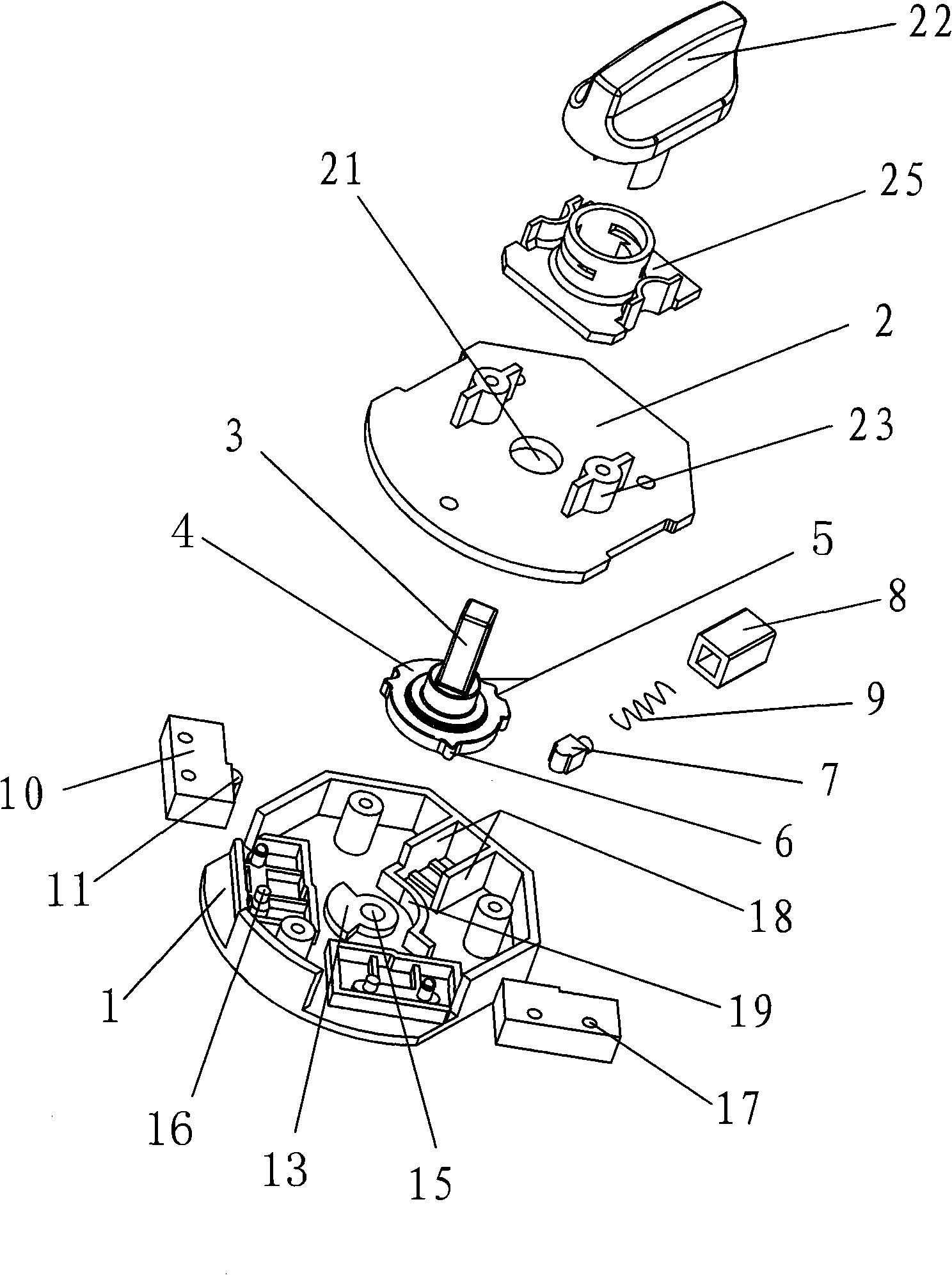
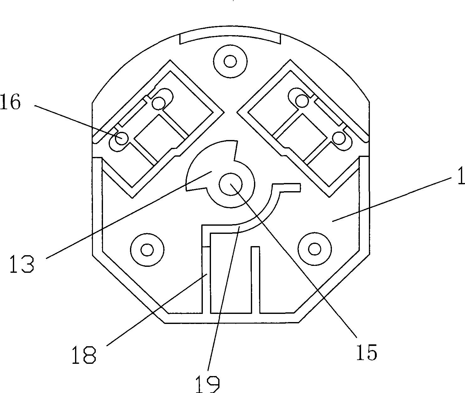
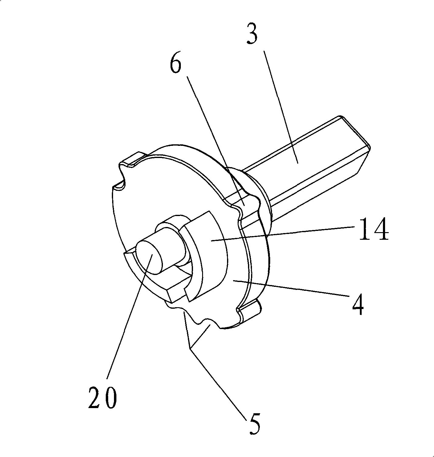
[0029] The internal structure of the insulating base 1 of the present invention can be designed as figure 2 The structure corresponding to the structure of the shaft 3 is as follows image 3 As shown, that is, the gear slot 5 is arranged on the edge of the turntable 4, and a spring box 8 is set on the insulating base 1. The spring box 8 is provided with a spring 9, and the spring top 7 is pressed tightly on the center by the centripetal spring force of the compression spring 9. In the gear slot 5 on the edge of the turntable 4, the operation of positioning and shifting can be realized by rotating the rotating shaft 3.

[0030] The internal structure of the insulating base 1 of the present invention can also be set as Figure 4 The structure corresponding to the structure of the shaft 3 is as follows Figure 5 As shown, that is, the gear slot 5 is arranged on the insulating base 1, a radial blind hole 12 is arranged on the turntable 4, and a spring 9 is arranged in the blind...


PUM


Abstract

A rotary switch comprises an insulating base, an insulating cover plate, a rotating shaft, a spring button, a spring and a contact box; wherein, the end of the rotating shaft is provided with a rotary disk; a gear groove and a push part are arranged on the edge of the rotary disk; a spring box is arranged on the insulating base; a compression spring is arranged in the spring box; the spring button is arranged against the gear groove on the edge of the rotary disk through the spring force; a movable contact and a static contact are arranged in the contact box; an insulation button is arranged on the contact box; the insulation button connects or disconnects the movable contact and the static contact through the push part; a sector block is arranged on the insulating base; the bottom of the rotary disk is provided with two stop blocks which control the turning angle of the rotating shaft together with the sector block, and a knob is arranged on the other end of the rotating shaft. In the rotary switch, the movable contact and the static contact are arranged in the insulated contact box, thus being simple to implement and having the biggest advantage of maintaining good conducting channel in the moist environment, preventing creepage and having high safety performance.

Description

technical field [0001] The invention relates to a switch, in particular to a rotary switch. Background technique [0002] In the prior art, the rotary switch often sets the elastic static contact piece on the switch base, sets the moving contact piece on the switch shaft, and connects or disconnects the moving contact piece and the static contact piece by rotating the switch shaft. The moving contact piece and the static contact piece are often exposed in the switch seat, such as a rotary switch with a patent number of 00227395.0, which includes an upper cover, a lower case, a switch shaft, and a conductive sheet. The lower case is provided with a side wall belt. There is a tooth-shaped cavity with a tooth-like structure, and a disc-shaped positioning block is arranged on the switch shaft. The positioning block is arranged in the center of the tooth-shaped cavity, and can be positioned and rotated. The positioning block is provided with a through hole in the radial direction...

Claims


Application Information

Patent Timeline
Patent Type & Authority Applications(China)
IPC IPC(8): H01H19/10H01H19/08
Inventor 祝杭军
Owner 湖州莱檬电子科技有限公司
Why Eureka
Try Eureka