Faraday polarization apparatus

A technology of Faraday rotator and magneto-optical rotation, which is applied in instruments, optics, nonlinear optics, etc. It can solve the problems of difficult consistency of combined magnetic field, high absorption coefficient, and difficult consistency control

Inactive Publication Date: 2013-06-05
北京飞波激光技术有限公司
View PDF4 Cites 0 Cited by
  • Summary
  • Abstract
  • Description
  • Claims
  • Application Information

AI Technical Summary

Problems solved by technology

[0002] One of the main uses of the Faraday rotator is to make optical isolators. At present, the optical isolators used in optical communication are made of magnetic optical materials with very high magnetic optical rotation coefficient and relatively low saturation magnetic field. In order to obtain a stable optical rotation angle, however, there is a relatively large defect in the current magnetic optical rotation materials with this performance, that is, for light with a wavelength less than 1200nm, the absorption coefficient is very high, which cannot be used in high-power applications, while for visible light Magneto-optical materials with low absorption of infrared light with a wavelength of less than 1200nm generally have a relatively low Verdet constant. Obtaining the required optical rotation angle requires a very high magnetic field strength and cannot work in a magnetic saturation state. Therefore, using this The optical rotator made of magnetic optical rotation material requires a high-strength magnetic field on the one hand, and on the other hand, for the case where the optical rotation angle is required to be more precise, the length of the magnetic optical rotation material and the axial (direction of beam propagation) magnetic field strength acting on the magnetic optical rotation material Correspondence is very strict
The method of combining magnetic fields can locally obtain a high-intensity magnetic field that is many times higher than that of a single magnet. It is difficult to control the consistency of the matching between them. Although the magnetic field can be matched by adjusting the length of the magnetic-optical material, or the length of the magnetic-optical material can be adjusted by adjusting the magnetic field, or the two matching methods can be used in combination, these methods are not suitable for mass production.
[0003] The U.S. patents "Compact enhanced performance optical isolator using a faraday rotator" (Patent No.: 5528415) and "Faraday rotator" (Patent No.: US 7,206,116 B2) both designed combined magnets capable of generating high-intensity magnetic fields, but the design of these two patents The local magnetic field strength of the combined magnet is not high enough in its working area (the area where the magnetic and optical materials are placed). Among them, the combined magnet designed by the patent No. 5528415 leaves a gap S in the working area between the two sets of combined magnets , which reduces the magnetic field strength in the working area, and the combined magnet of the patent design of the patent No. US 7,206,116 B2, the working area is all placed in the magnetic cylinder composed of a single piece of iron, and the magnetic field strength of this single piece of magnet is much lower than that of The magnetic field strength of the composite magnet
In addition, the combined magnet with patent No. 5528415 adopts the method of adjusting the gap between the combined magnet components to adjust the magnetic field strength in the working area, which is difficult to adjust

Method used


Image

  • Faraday polarization apparatus
  • Faraday polarization apparatus
  • Faraday polarization apparatus

Examples


Embodiment 1

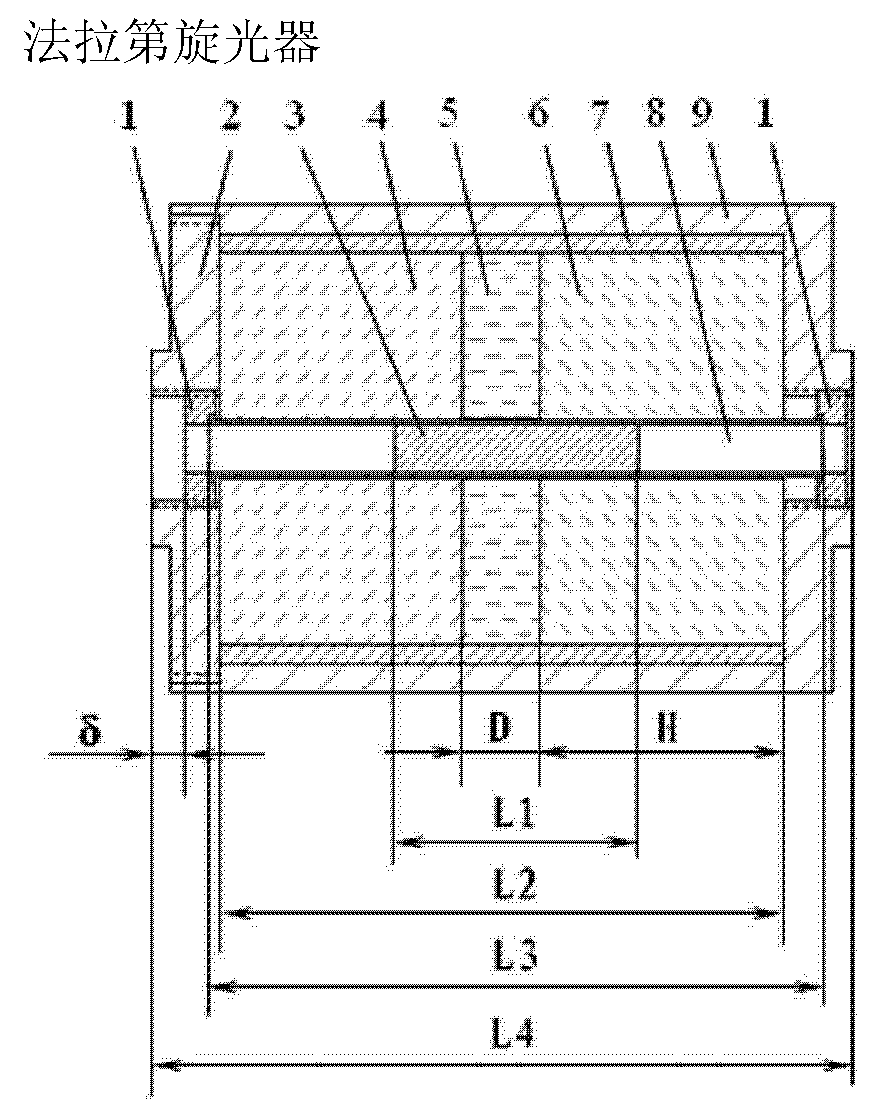
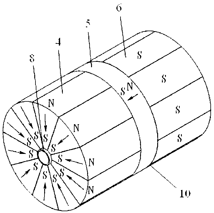
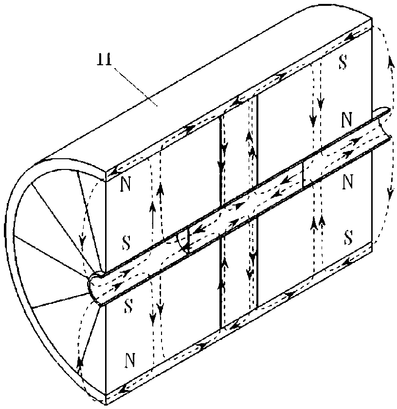
[0019] see Figures 1 to 3 , the Faraday rotator provided by the present invention consists of an adjusting plate 1, an end cap 2, a magnetic rotator 3, a first fan-shaped magnetic block 4, an intermediate magnetic block 5, a second fan-shaped magnetic block 6, a magnetic shielding sleeve 7, and a magnetic rotator The sleeve 8 and the shell 9 are composed of a composite magnet 11 composed of the first fan-shaped magnetic block 4, the second fan-shaped magnetic block 6, the middle magnetic block 5 and the magnetic shielding sleeve 7, and the adjusting piece 1, the end cover 2, and the magnetic rotation rod The sleeve 8 and the shell 9 complete the adjustment and fixation of the relative position between the compound magnet 11 and the magnetic rotation rod 3 . After the composite magnet 11 is placed in the shell 9, it is compressed with the end cover 2. There is a screw hole at the position coaxial with the inner hole of the composite magnet 11 on the shell 9 and the end cover 2...

Embodiment 2

[0025] The magnetic rotation rod sleeve 8 can be divided into 2 sections or 3 sections according to needs, so as to facilitate the fixing of the magnetic rotation rod 3 .


PUM


Abstract

The invention relates to a Faraday polarization apparatus, which belongs to an optical passive device and is used for rotating the polarization direction of light according to the direction of a magnetic field. The Faraday polarization apparatus comprises a compound magnet, and fixing and adjusting parts, wherein the compound magnet is formed by clamping a central magnet block (5) with two groupsof cylindrical magnet units respectively comprising n first fan-shaped magnet blocks (4) and n second fan-shaped magnet blocks (6) in a magnetic shielding sleeve (7) with high magnetic permeability; the compound magnet is pressed tightly by an end cover (2) after being arranged in a casing (9); and a magnetic rotation rod sleeve (8) fixed with a magnetic rotation rod (3) is positioned in an innerhole of the compound magnet, both ends of the magnetic rotation rod sleeve are clamped by two adjustment sheets (1), and the relative position of the magnetic rotation rod (3) and the compound magnetcan be adjusted by adjusting the two adjustment sheets (1) at two ends simultaneously to achieve the aim of adjusting an rotation angle.

Description

technical field [0001] The invention relates to a Faraday optical rotator, in particular to a high-power and large-aperture Faraday optical rotator with an optical rotation angle of 45 degrees made of a magnetic optical rotation material transparent to the 550nm to 1600nm band. Background technique [0002] One of the main uses of the Faraday rotator is to make optical isolators. At present, the optical isolators used in optical communication are made of magnetic optical materials with very high magnetic optical rotation coefficient and relatively low saturation magnetic field. In order to obtain a stable optical rotation angle, however, there is a relatively large defect in the current magnetic optical rotation materials with this performance, that is, for light with a wavelength less than 1200nm, the absorption coefficient is very high, which cannot be used in high-power applications, while for visible light Magneto-optical materials with low absorption of infrared light w...

Claims


Application Information

Patent Timeline
Patent Type & Authority Patents(China)
IPC IPC(8): G02F1/09
Inventor 伍峰
Owner 北京飞波激光技术有限公司
Why Eureka
Try Eureka