Supercharge Your Innovation With Domain-Expert AI Agents!

Turbocharger

A technology of turbochargers and turbines, which is applied in the direction of machines/engines, gas turbine devices, mechanical equipment, etc., and can solve problems such as leakage, increased leakage, and increased wear

Active Publication Date: 2009-09-23
BORGWARNER INC
View PDF1 Cites 10 Cited by
  • Summary
  • Abstract
  • Description
  • Claims
  • Application Information

AI Technical Summary

Problems solved by technology

Depending on the amount of play of the lever / flap connection, this can lead to the flap being subjected to an uneven pressure on its periphery or to the flap not being in full contact with the seal seat, which leads to a significant increase in leakage
Said problem cannot be solved by increasing the play of the coupling, since this increases the relative movement of the flap shortly before it abuts against the sealing seat, which causes increased wear during operation and thus cause an increase in leakage

Method used


Image

  • Turbocharger
  • Turbocharger
  • Turbocharger

Examples


Embodiment Construction

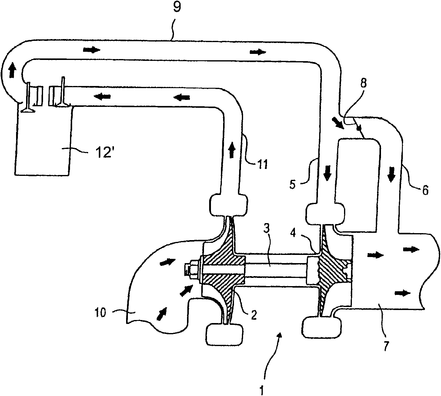
[0012] figure 1 A schematically highly simplified illustration of a turbocharger 1 according to the invention is shown.

[0013] The turbocharger 1 has a compressor 2 , the compressor wheel of which is connected via a shaft 3 to the turbine wheel of a turbine 4 . The turbine 4 has an exhaust gas inlet 5 which is connected to an exhaust gas line 9 of the internal combustion engine.

[0014] The turbine 4 also has an exhaust outlet 7 .

[0015] figure 1 Also shown is a bypass line 6 which branches upstream of the exhaust gas inlet 5 of the turbine inlet and leads directly to the exhaust gas outlet 7 so that the turbine 4 is bypassed by said bypass line 6 .

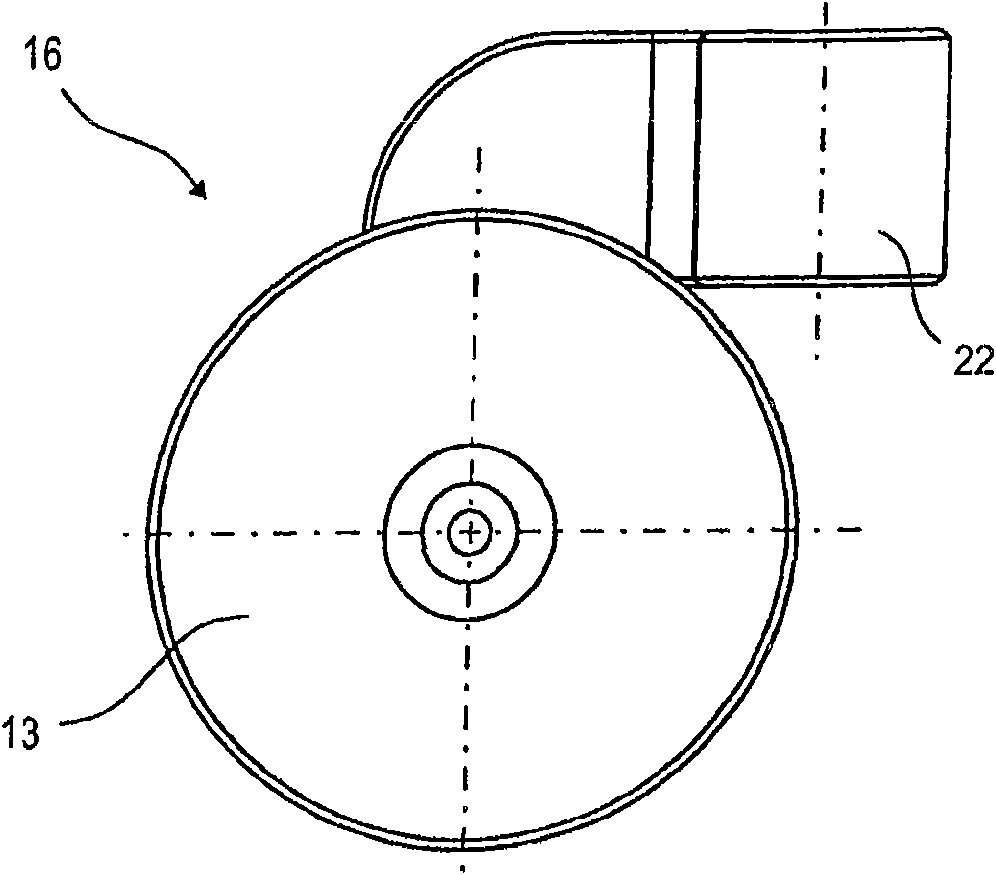
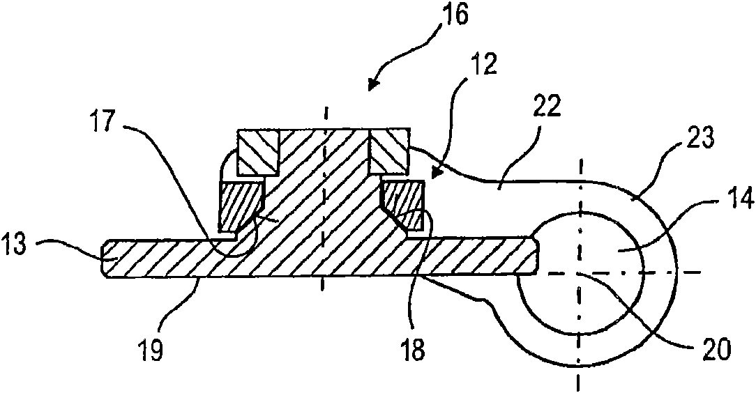
[0016] Arranged in the bypass line 6 is a blocking element 8 which can, for example, be designed as a so-called "wastegate". The blocking element 8 has an inflation pressure regulating flap 16 designed according to the invention, which is explained in more detail below based on various embodiments.

[0017] For complete...


PUM


Abstract

The invention relates to a turbocharger (1) comprising a compressor (2), a turbine connected to the compressor (2) by means of a shaft (3) and provided with an exhaust inlet (5) and an exhaust outlet (7), and a bypass line (6) which branches off from the exhaust inlet (5), bypassing the turbine, and leads to the exhaust outlet in which a boost-pressure regulating flap is arranged, said regulatingflap comprising a flap plate (13) which is connected to a flap shaft (14) by means of a connecting device (12).

Description

technical field [0001] The invention relates to a turbocharger according to the preamble of claim 1 , claim 5 or claim 6 . Background technique [0002] A turbocharger of this type is known from EP 1 626 212 A1. The turbocharger of said document has a regulating flap which is arranged in the exhaust bypass line for regulating the charging pressure. Due to their geometry, the regulating flap is only suitable for small flap diameters or low mass flow velocities. The geometry is characterized firstly by the fact that the axis of rotation of the flap shaft is not located in the sealing plane of the flap, but is offset relative thereto, and secondly by a cylindrical connection between the lever and the flap device. Under load, the tilting of the flap axis due to the bearing play has the result that the point of contact between the flap and the lever moves away from the theoretical center and an eccentrically acting pressure is generated on the plate. Depending on the amount o...

Claims


Application Information

Patent Timeline
IPC IPC(8): F02B37/18
CPCF05D2250/292F02C6/12F01D17/105F05D2220/40Y02T10/144F02B37/186F02B37/183Y02T10/12F02B37/18F02B37/12F02B39/00F16K1/18
Inventor S·科克T·科纳R·维克特
Owner BORGWARNER INC
Features
  • R&D
  • Intellectual Property
  • Life Sciences
  • Materials
  • Tech Scout
  • Unparalleled Data Quality
  • Higher Quality Content
  • 60% Fewer Hallucinations
Learn More