Compact optical detection system

A detection system and detector technology, applied in the direction of material analysis, measuring devices, scientific instruments, etc. through optical means, can solve problems such as huge, expensive, and complex detectors

Inactive Publication Date: 2009-09-23
AGENCY FOR SCI TECH & RES
View PDF0 Cites 19 Cited by
  • Summary
  • Abstract
  • Description
  • Claims
  • Application Information

AI Technical Summary

Problems solved by technology

These detectors can be complex, large, or expensive, and often require special operating conditions, such as working in complete darkness or at low temperatures

Method used


Image

  • Compact optical detection system
  • Compact optical detection system
  • Compact optical detection system

Examples


example 1

[0088] A miniaturized fluorescent system with a size of 30mm×30mm×11mm was designed and tested.

[0089] The properties of the detection system are determined by measuring a series of dilutions of the fluorescent pigment fluorescein. The detection limit was found to be 1.96nmol / L, which was greater than the detection limit required for applications such as real-time PCR.

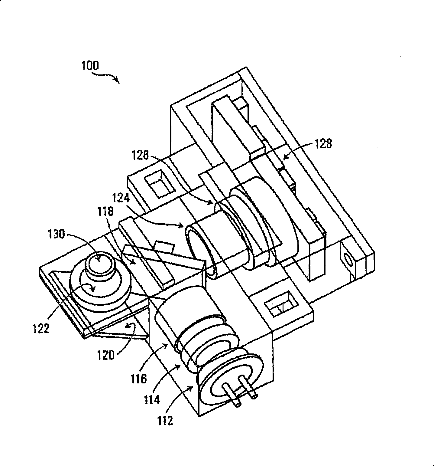
[0090] The optical detection system has two parts: an excitation part and a detection part. The excitation part included a cyan LED type ETG-5CE490-15 (ETG Corporation) as a light source. The LED has a peak emission wavelength of 490nm, a luminous intensity of 6cd (Cancelles), and a viewing angle of 15°. Due to the viewing angle of the light source, power loss can be observed in the optical path. Therefore, to collimate the light, the top of the LED plastic cover was cut off by milling 0.5mm vertically from the LED chip. Next, the cut surfaces were flattened with aluminum oxide waterproof sandpaper and a...

example 2

[0116] Combined with the optical detection system described above, a miniaturized and economical real-time PCR made of microfabricated silicon was fabricated.

[0117] Here, a compact autonomous real-time RT-PCR device is described as having dimensions of 7 cm x 7 cm x 3 cm and weighing 75 g, or in a second embodiment, having dimensions of 10 cm (diameter) x 6 cm (height) and weighing 150 g.

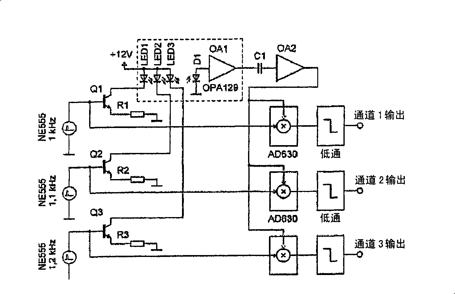
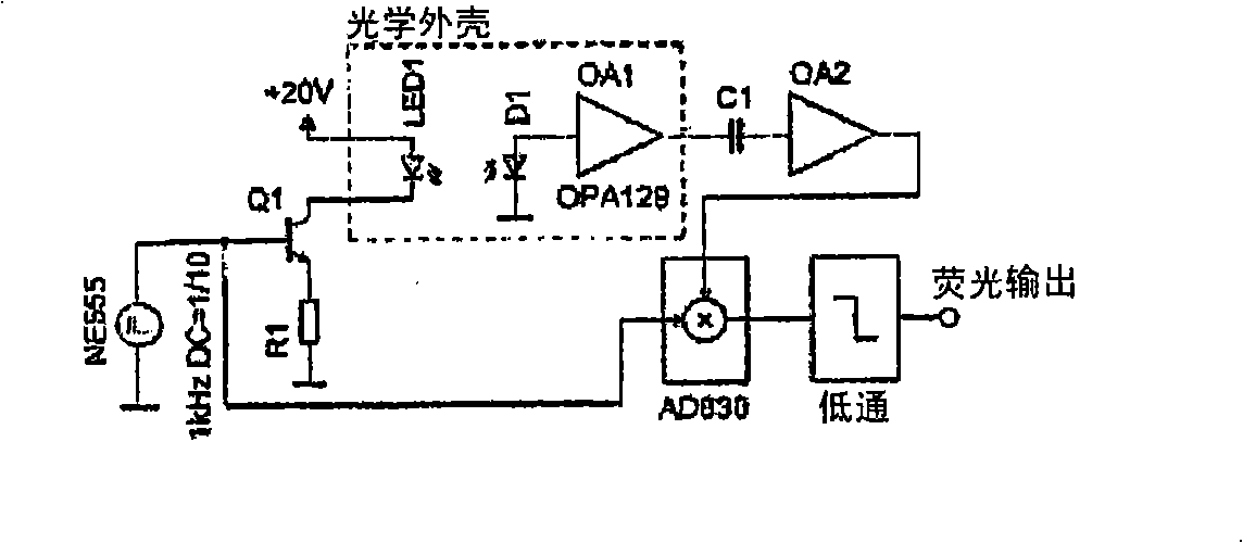
[0118] Integrate the PCR unit with a miniaturized fluorescent detection system and all electronics necessary for the system to work. A turquoise LED (490mm peak excitation wavelength) was powered by a current pulse with a peak amplitude of 100mA. The photocurrent detected by the photodiode is processed by a lock-in amplifier, making the optical system independent of ambient light.

[0119] Since the device consumes only 3w, a 12Ah battery can be used to power the thermal cycler device for up to 12 hours. The compact size of the thermal cycler device and its power consumption ensure its...

example 3

[0135] Portable Thermal Cycler Devices Tested for Genetic Analysis of Infectious Diseases. Validation of the thermal cycler device by detection of RNA isolated from avian influenza virus (H5NI) using the RNAMaster SYBR Green I RT-PCR Kit (Roche) with PCR primers developed at the Singapore Institute of Molecular and Cell Biology RT-PCR performance.

[0136] Reverse transcription was performed at a temperature of 61 °C for 2 minutes and 30 seconds, followed by a 30-second hot start. Amplification of 50 PCR cycles was performed in the following manner: 95°C for 3 seconds (denaturation), 50°C for 15 seconds (annealing), and 72°C for 20 seconds (renaturation). Once the PCR cycle is complete, at 1 °C s -1 conversion rate to perform melting curve analysis. The total time required to detect viral RNA was 14 minutes.

[0137] Figure 11 Shown is the real-time RT-PCR result of detecting H5N1 virus using the miniaturized thermal cycler device. The critical threshold for detection w...


PUM

PropertyMeasurementUnit
luminous intensityaaaaaaaaaa
transmittivityaaaaaaaaaa

Abstract

A detection system is provided, the detection system comprising a light source that generates excitation light having a wavelength sufficient to excite a fluorophore in a sample; an excitation filter positioned along a first line along a path of the excitation light, the excitation filter transmitting the excitation light from the light source; a beam splitter positioned along the first line, the beam splitter reflecting the excitation light transmitted by the excitation filter along a second line toward a mirror positioned on one side of the beam splitter, and passing emitted light reflected along the second line; the mirror, positioned to reflect the excitation light from the beam splitter to the fluorophore in the sample along a third line, normal to both the first and second lines, wherein the mirror further reflects emitted light emitted along the third line, along the second line toward the beam splitter; an emission filter positioned along the second line, on a second side of the beam splitter; and a detector that detects the emitted light transmitted by the emission filter.

Description

[0001] Cross References to Related Applications [0002] This application claims priority to US Provisional Patent Application 60 / 839,678, filed August 24, 2006, which is hereby incorporated by reference in its entirety. technical field [0003] The present invention relates generally to optical detection systems, and more particularly to compact optical detection systems for detecting fluorescent signals. Background technique [0004] Laboratory-on-a-chip systems have been developed for various applications such as new drug development, pathogen detection, etc. These systems process biological or chemical samples and provide quantitative or qualitative detection of target molecules or particles. Such systems use miniaturized components and are designed to be portable, enabling on-site sample testing. [0005] In particular, the need to use portable devices to detect biological weapons, pathogens, or viruses in the field has prompted the development of new types of portabl...

Claims


Application Information

Patent Timeline
Patent Type & Authority Applications(China)
IPC IPC(8): G01N21/64G01N33/533
CPCG01N2201/0693G01N21/6428G01N2201/0625G01N2021/6441G01N2201/0221G01N21/0332B01L2300/1827G01N2201/0627G01N21/76G01N2021/6419B01L7/52G01N21/763G01N2021/6421G01N21/645B01L3/5088B01L2200/147
Inventor 帕维尔·纽泽尔于尔根·皮珀卢卡斯·诺瓦克
Owner AGENCY FOR SCI TECH & RES
Why Eureka
Try Eureka