Polarized head-mounted projection display

a projection display and head-mounted technology, applied in the direction of projectors, polarising elements, instruments, etc., can solve the problems of low luminance transfer efficiency of optical systems, and inability to apply such information displays outdoors or in scenarios

Active Publication Date: 2010-01-07
THE ARIZONA BOARD OF REGENTS ON BEHALF OF THE UNIV OF ARIZONA
View PDF8 Cites 137 Cited by
  • Summary
  • Abstract
  • Description
  • Claims
  • Application Information

AI Technical Summary

Problems solved by technology

Designing a wide field-of-view (FOV), compact and non-intrusive OST-HMD, has been a challenge.
However, the images appearing on optical see-through displays commonly lack brightness and contrast compared to the direct view of a real-world scene.
The problem of low image brightness and contrast is worsened by any light attenuation through any optical combiner interface required in see-through displays, resulting in low luminance transfer efficiency of the optical system.
Consequently, such displays are usually used in dim environments, reducing the feasibility of applying such information displays outdoor or in scenarios where well-lit environments such as in an operation room are necessary.
This luminance imposes significant restrictions on the lighting conditions of working environments and limits applications demanding well-lit environments.

Method used


Image

  • Polarized head-mounted projection display
  • Polarized head-mounted projection display
  • Polarized head-mounted projection display

Examples


examples

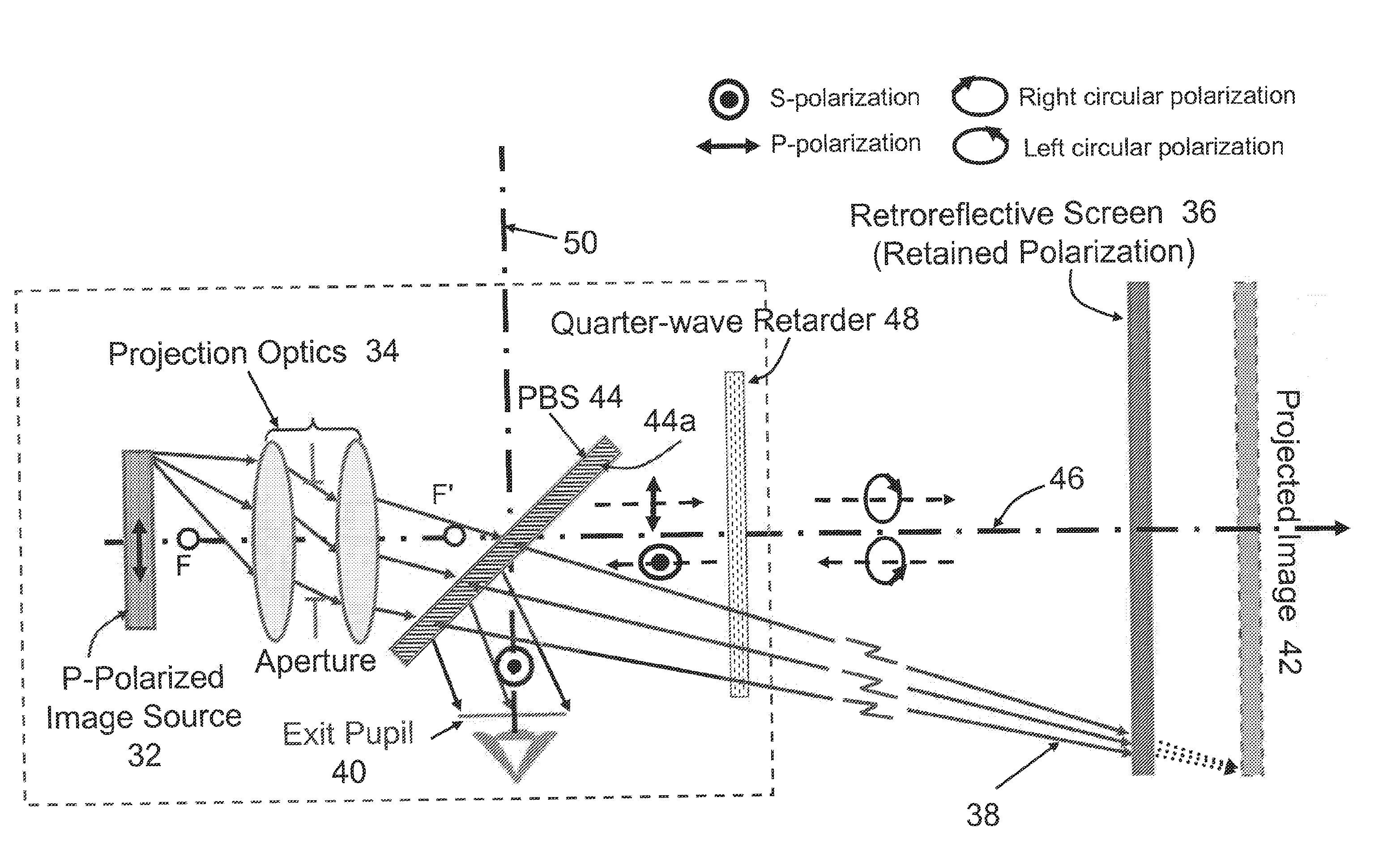
[0099]The fabricated wire-grid polarizing beam splitters and retarders were tested for FOV dependence with an Axiometric polarimeter at a 550 nm wavelength. The reflectance for S-polarized light is approximately 93% for zero-degree field angle, varying between 88% and 96% for field angles in the range of ±30°. The transmittance for P-polarized light is approximately 87% for zero-degree field angle, varying between 82% and 60% for field angles in the range of ±30°. The zero-degree field corresponds to a 45-degree incidence angle on the PBS, and a positive field angle indicates that a ray impinges on the PBS at an angle less than 45 degrees. At the zero-degree field, the ratio of the reflectance for S-polarized light to P-polarized light is about 95, and the ratio of the transmittance for P-polarized light to S-polarized light is about 480.

[0100]The transmittance of the retarder in this embodiment was approximately constant across the entire FOV (less than 1.5% of variation). The reta...


PUM

PropertyMeasurementUnit
luminanceaaaaaaaaaa
luminanceaaaaaaaaaa
luminanceaaaaaaaaaa

Abstract

An image display system and associated method for image displaying The system includes an image source configured to generate image light, projection optics configured to project the image light, and a polarizing beam splitter optically coupled to the projection optics and configured to propagate into a first optical path first polarized light having a first polarization and to propagate into a second optical path second polarized light having a second polarization The system includes a quarter wave converter disposed in the first optical path and configured to rotate the first polarization by a quarter phase as the first polarized light first passes through the quarter wave converter, and includes a reflective screen disposed in the first optical path and configured to reflect rotated first polarized light from the quarter wave converter back through the quarter wave converter for further quarter phase rotation.

Description

CROSS REFERENCE TO RELATED APPLICATIONS[0001]This invention is related to and claims priority to U.S. Ser. No. 60 / 880,980, entitled “Design of a Bright Polarized Head-Mounted Projection Display,” filed Jan. 18, 2007. The entire contents of U.S. Ser. No. 60 / 880,980 are incorporated herein by reference.STATEMENT REGARDING FEDERALLY SPONSORED RESEARCH[0002]This invention was made with government support under IIS0534777 awarded by the National Science Foundation. The government has certain rights in the invention.BACKGROUND OF THE INVENTION[0003]1. Field of the Invention[0004]This invention is related to the field of head-mounted displays (HMD) and methods of manufacturing such displays.[0005]2. Description of the Related Art[0006]Mixed- and augmented reality (MR-AR) technology is a paradigm where computer-generated digital information is selectively superimposed upon a real-world scene to supplement a user's sensory perception of the physical environment. It has been explored for a wi...

Claims


Application Information

Patent Timeline
Patent Type & Authority Applications(United States)
IPC IPC(8): G02F1/1335G03B21/14
CPCG02B5/30G02B13/00G02B27/0172G02B2027/0178G02B2027/0134G02B2027/0138G02B2027/0118
Inventor HUA, HONG
Owner THE ARIZONA BOARD OF REGENTS ON BEHALF OF THE UNIV OF ARIZONA
Why Eureka
Try Eureka