

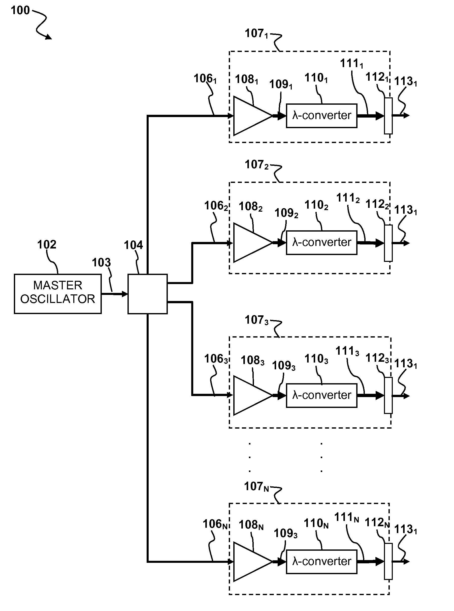
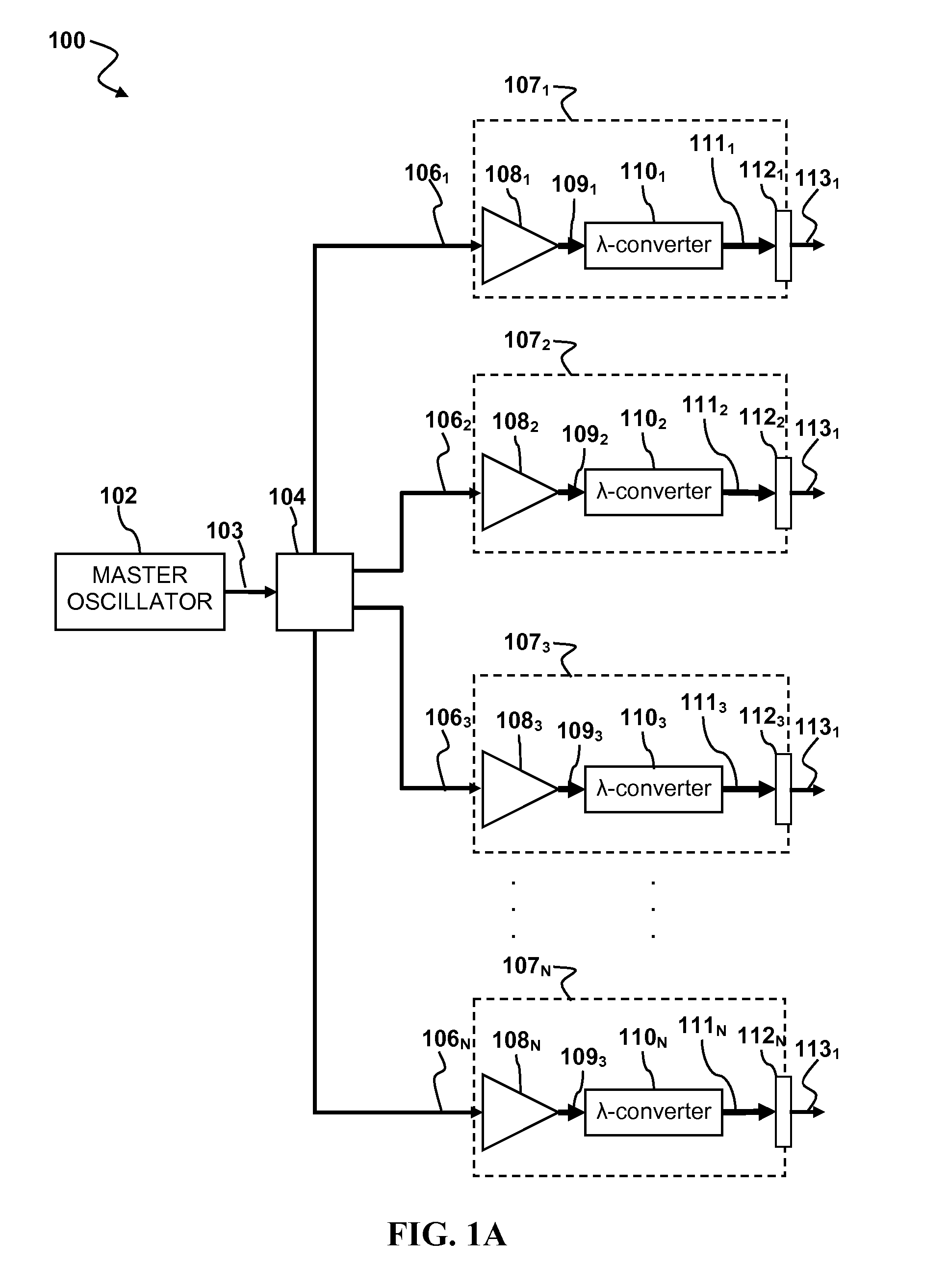
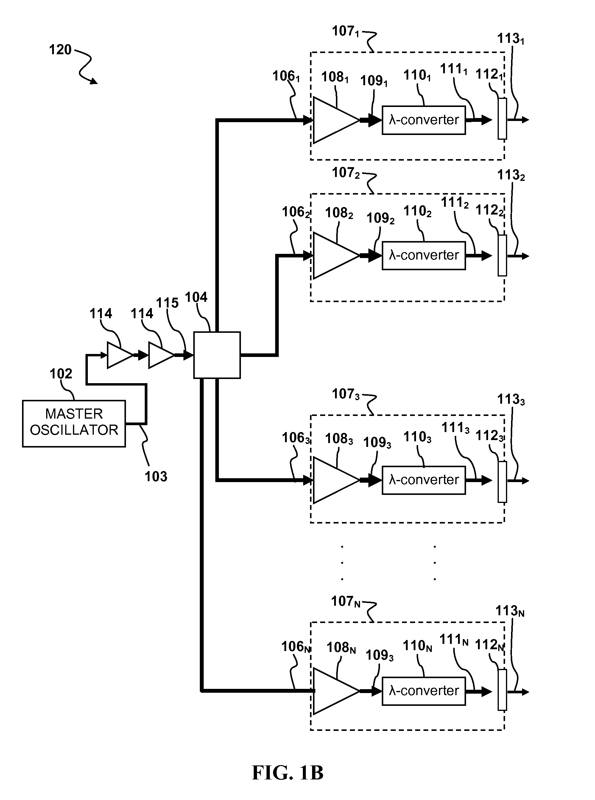
Laser apparatus having multiple synchronous amplifiers tied to one master oscillator
a laser system and amplifier technology, applied in the field of lasers, can solve the problems of complex, unreliable, and/or high cost, and achieve the effects of reducing the variation in pulse characteristics, arbitrary increase in system output power, and reducing the cost and scalability of multiple output wavelength conversion
- Summary
- Abstract
- Description
- Claims
- Application Information
AI Technical Summary
Benefits of technology
Problems solved by technology
Method used
Image

Examples
Embodiment Construction
[0015]Although the following detailed description contains many specific details for the purposes of illustration, anyone of ordinary skill in the art will appreciate that many variations and alterations to the following details are within the scope of the invention. Accordingly, the exemplary embodiments of the invention described below are set forth without any loss of generality to, and without imposing limitations upon, the claimed invention.
GLOSSARY
[0016]As used herein:
[0017]The indefinite article “A” or “An” refers to a quantity of one or more of the item following the article, except where expressly stated otherwise.
[0018]Beam Splitter refers to an optical device capable of splitting a beam of light into two or more parts.
[0019]Cavity or Optically Resonant Cavity refers to an optical path defined by two or more reflecting surfaces along which light can reciprocate or circulate. Objects that intersect the optical path are said to be within the cavity.
[0020]Continuous wave (CW)...
PUM
| Property | Measurement | Unit |
|---|---|---|
| total output power | aaaaa | aaaaa |
| vacuum wavelength | aaaaa | aaaaa |
| vacuum wavelength | aaaaa | aaaaa |
Abstract
Description
Claims
Application Information