Laser apparatus having multiple synchronous amplifiers tied to one master oscillator

Active Publication Date: 2007-10-25
DISCO CORP
View PDF23 Cites 74 Cited by
  • Summary
  • Abstract
  • Description
  • Claims
  • Application Information

AI Technical Summary

Benefits of technology

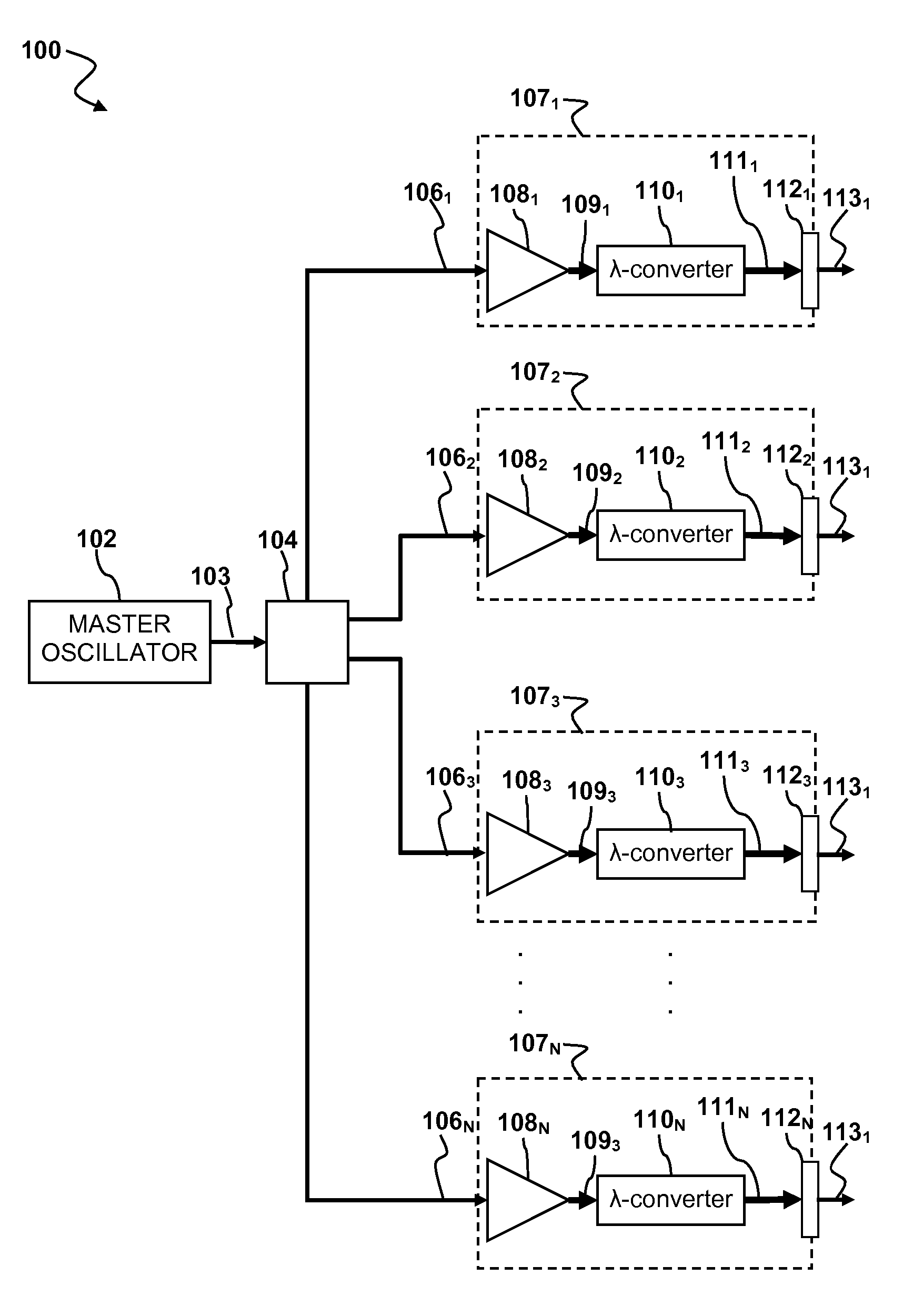
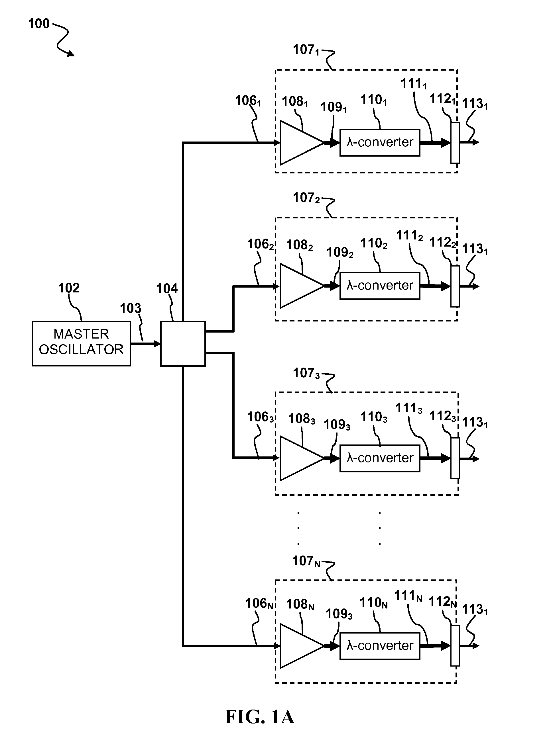
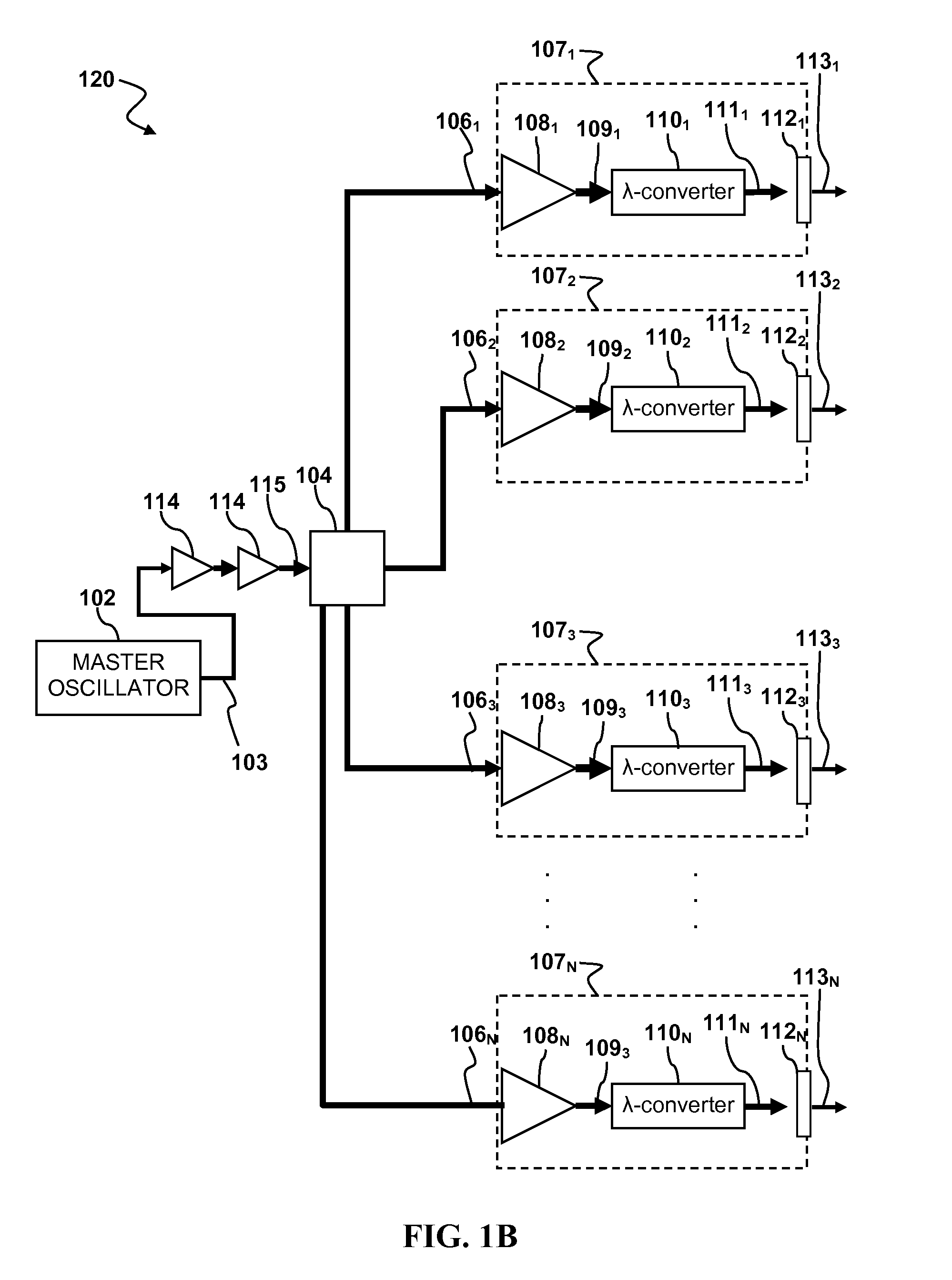
[0076] Embodiments of the present invention have a number of practical applications. For example, as shown in FIGS. 6A-6B laser systems having multiple amplified and Wavelength-converted outputs generated from a single master oscillator signal may find application in laser material processing systems. As shown in FIG. 6A, a laser material processing system 600 may include a master oscillator 602 optically coupled by a beam splitter 604 to N optical power amplifiers 6081, 6082 . . . 608N. Each of the N optical power amplifiers 6081, 6082 . . . 608N may be optically coupled to a corresponding one of N optical wavelength converters 6101, 6102 . . . 610N. Output coupler lenses 6121, 6122 . . . 612N may couple amplified and wavelength-converted outputs 6131, 6132, 6133 . . . 613N from the optical wavelength converters 6101, 6102 . . . 610N, respectively to a single target 615 in parallel. Alternatively, the wavelength-converted amplified outputs may be coupled to different targets 615. The targets 615 may move relative to the output couplers 6121, 6122 . . . 612N to allow for machining of different portions of the workpiece, e.g., by drilling multiple parallel rows of holes or by milling multiple parallel slots or grooves. Such a parallel processing configuration can enhance the processing throughput of workpieces, thereby speeding up production and lower costs.
[0077] The system 600 in FIG. 6A is configured to process a single side of one or more targets with multiple amplified wavelength-converted outputs. Alternatively, as shown in FIG. 6B, a laser material processing system 620 may be configured to process two or more different locations on the same or different targets simultaneously. Specifically, in the system 620 a master signal 621 from a master oscillator 622 is split into two branches by a beam splitter 624. One branch of the master signal 621 is coupled to amplifiers 6281, 6282, wavelength converters 6301, 6302 and output couplers 6321, 6322 that couple outputs 6331, 6332

Problems solved by technology

However, splitting the amplified output reduces the available power for each process operation.
This can be a significant problem when there exists a minimum (or an optimum) average power and/or peak power for a particular operation.
It is generally difficult to significantly scale the total system output power of a multiple output head laser system without making architectural changes.
This tends to be complicated, unreliable, and/or expensive.
Often the laser system puts limits on the pulse energy.
Also, many laser systems put constraints on the relations

Method used


Image

  • Laser apparatus having multiple synchronous amplifiers tied to one master oscillator
  • Laser apparatus having multiple synchronous amplifiers tied to one master oscillator
  • Laser apparatus having multiple synchronous amplifiers tied to one master oscillator

Examples


Embodiment Construction

[0015] Although the following detailed description contains many specific details for the purposes of illustration, anyone of ordinary skill in the art will appreciate that many variations and alterations to the following details are within the scope of the invention. Accordingly, the exemplary embodiments of the invention described below are set forth without any loss of generality to, and without imposing limitations upon, the claimed invention.

GLOSSARY

[0016] As used herein:

[0017] The indefinite article “A” or “An” refers to a quantity of one or more of the item following the article, except where expressly stated otherwise.

[0018] Beam Splitter refers to an optical device capable of splitting a beam of light into two or more parts.

[0019] Cavity or Optically Resonant Cavity refers to an optical path defined by two or more reflecting surfaces along which light can reciprocate or circulate. Objects that intersect the optical path are said to be within the cavity.

[0020] Continuo...


PUM

PropertyMeasurementUnit
Timeaaaaaaaaaa
Poweraaaaaaaaaa
Efficiencyaaaaaaaaaa

Abstract

Laser apparatus and methods involving multiple amplified outputs are disclosed. A laser apparatus may include a master oscillator, a beam splitter coupled to the master oscillator, and two or more output heads optically coupled to the beam splitter. The beam splitter divides a signal from the master oscillator into two or more sub-signals. Each output head receives one of the two or more sub-signals. Each output head includes coupling optics optically coupled to the beam splitter. An optical power amplifier is optically coupled between the beam splitter and the coupling optics. Optical outputs from the two or more output heads do not spatially overlap at a target. The master oscillator signal may be pulsed so that optical outputs of the output heads are pulsed and substantially synchronous with each other.

Description

FIELD OF THE INVENTION [0001] This invention generally relates to lasers and more particularly to laser systems with multiple output heads that produce synchronized outputs. BACKGROUND OF THE INVENTION [0002] High powered lasers have many applications in which an intense beam of coherent light is focused onto a substrate or other target. Many high-power laser systems utilize a master oscillator power amplifier (MOPA) architecture. In a MOPA laser system a laser signal from a seed laser, referred to as a master oscillator is fed into an optical amplifier which amplifies the power of the master signal. MOPA architecture allows precise pulsing of the amplified output. MOPA-based laser systems are often used in high power applications, such as laser micromachining. [0003] In certain laser applications it is sometimes desirable to simultaneously apply laser light to multiple locations on the target or to simultaneously process multiple targets. For example, in laser micromachining it may...

Claims


Application Information

Patent Timeline
IPC IPC(8): H01S3/30H01S3/10H01S3/22H01S3/223
CPCB23K26/067B23K26/0673B23K26/0676B23K26/0884H01S3/2383H01S3/005H01S3/2308H01S3/2316B23K2201/006B23K2101/006
Inventor LEONARDO, MANUEL J.BYER, MARK W.SMOLIAR, LAURA A.
Owner DISCO CORP
Why Eureka
Try Eureka