Electric compressor
一种电动压缩机、电动机的技术,应用在发动机元件、机器/发动机、液体燃料发动机等方向,能够解决组装性变差、难以密封连接器、机壳轴线方向长度变长等问题
- Summary
- Abstract
- Description
- Claims
- Application Information
AI Technical Summary
Problems solved by technology
Method used
Image

Examples
no. 1 Embodiment approach
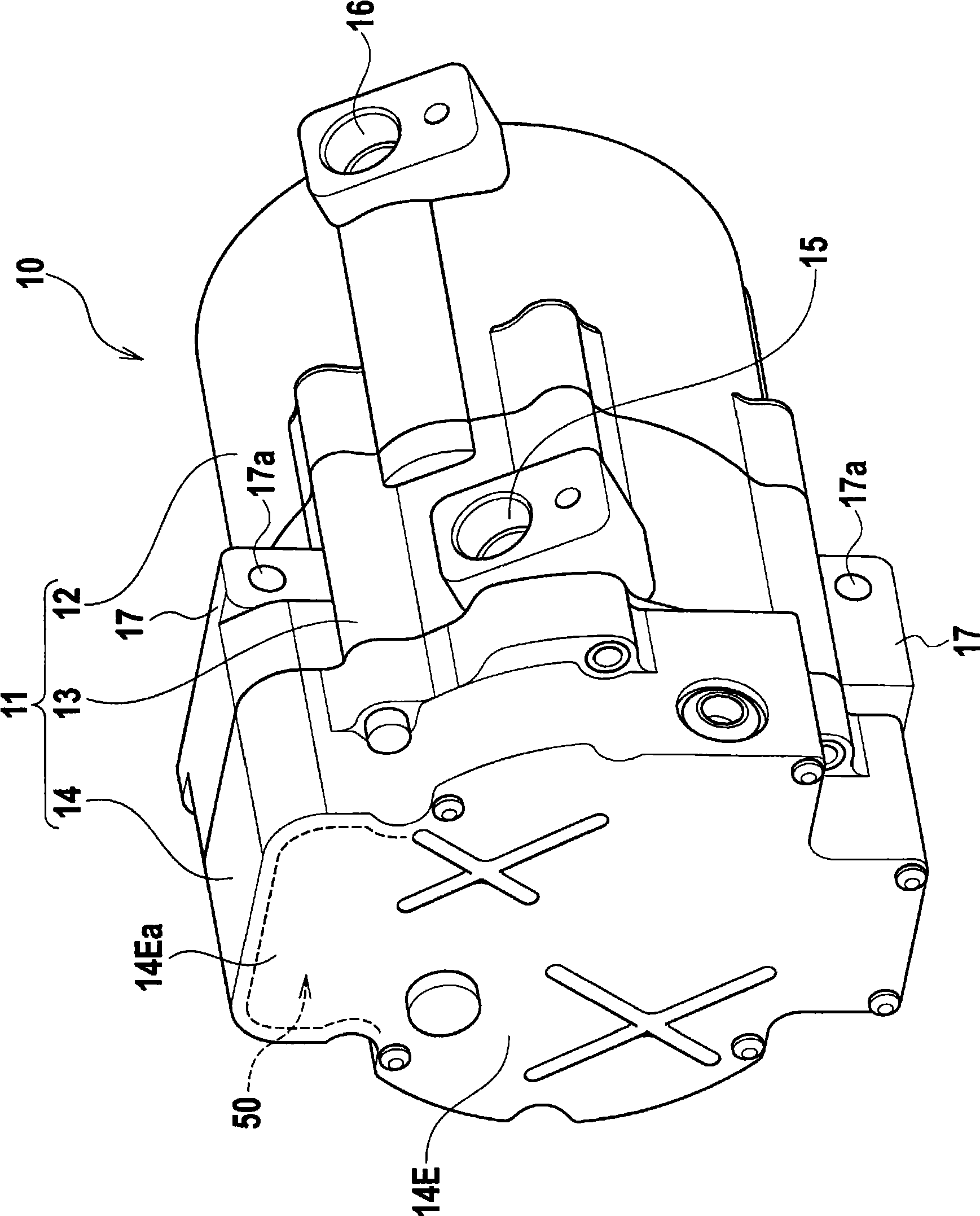
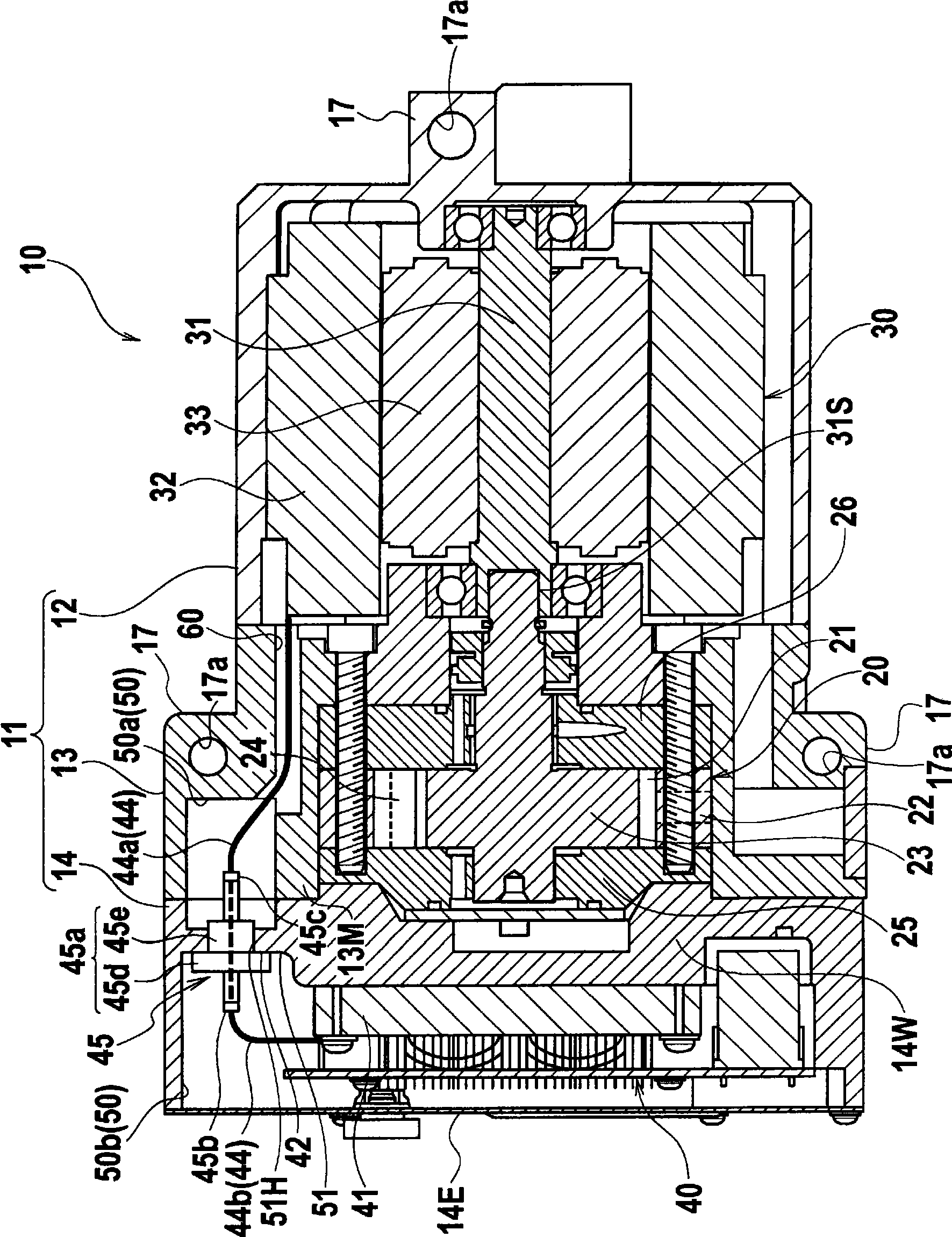
[0020] figure 1 is an overall perspective view of the electric compressor of this embodiment, figure 2 It is a longitudinal sectional view of the electric compressor.
[0021] Such as figure 1 , figure 2 As shown, in the electric compressor 10 of this embodiment, along the axis direction ( figure 2 The rear case 12 , the middle case 13 , and the front case 14 , which are divided into three in the middle, left, and right directions), are combined to form the cabinet 11 . And, if figure 2 As shown, the compression mechanism unit 20 is accommodated in the middle housing 13 , the motor 30 is accommodated in the rear housing 12 , and the motor drive circuit unit 40 for controlling energization of the motor 30 is accommodated in the front housing 14 .
[0022] And, if figure 1 As shown, the refrigerant introduced into the casing 11 from the inlet 15 formed on the middle casing 13 is compressed by the compression mechanism part 20 and discharged from the discharge port 16 f...
no. 2 Embodiment approach
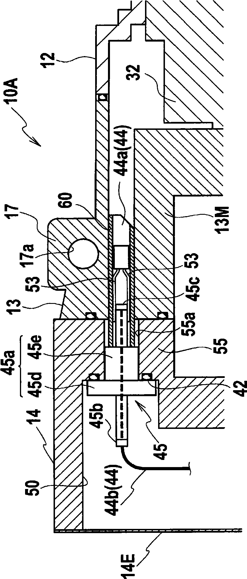
[0050] image 3 It is an enlarged view around the connector of the electric compressor of this embodiment. The electric compressor 10A includes the same constituent elements as the electric compressor 10 of the first embodiment described above. Therefore, in the following, common reference numerals are assigned to these same constituent elements, and overlapping descriptions are omitted.
[0051] The electric compressor 10A of this embodiment differs from the electric compressor 10 of the above-mentioned first embodiment in that the bulged space portion 50 is not formed so as to straddle the front casing 14 and the middle casing 13 , but is formed in the front casing. within 14.
[0052] An insertion hole 55 a for mounting the hermetic terminal 45 is formed on a wall portion 55 of the peripheral wall of the bulging space portion 50 of the front case 14 that engages with the end surface of the middle case 13 . In addition, a communication hole 60 is formed through the middle...
no. 3 Embodiment approach
[0058] Figure 4 It is an enlarged view around the connector of the electric compressor of this embodiment. Hereinafter, common reference numerals are assigned to the same constituent elements as those of the above-mentioned second embodiment, and overlapping descriptions will be omitted.
[0059] Such as Figure 4 As shown, in the electric compressor 10B of the present embodiment, the axial direction of the terminal portion 45 c on the side of the mounting bracket 17 of the hermetic terminal 45 is arranged obliquely toward the radial center side of the casing 11 so as to avoid the mounting bracket 17 . .
[0060] With this configuration, the sealed terminal 45 and the mounting bracket 17 can be mounted without additionally enlarging the space of the housing 11 . That is, the sealing terminal 45 and the mounting bracket 17 can be arranged so as to be close to each other in the axial direction, thereby reducing the size of the housing 11 accordingly.
PUM
 Abstract
Description
Claims
Application Information
 - R&D
- Intellectual Property
- Life Sciences
- Materials
- Tech Scout
- Unparalleled Data Quality
- Higher Quality Content
- 60% Fewer Hallucinations
Browse by: Latest US Patents, China's latest patents, Technical Efficacy Thesaurus, Application Domain, Technology Topic, Popular Technical Reports.
© 2025 PatSnap. All rights reserved.Legal|Privacy policy|Modern Slavery Act Transparency Statement|Sitemap|About US| Contact US: help@patsnap.com