
Part feeder, and surface mounting machine

A component supply and component technology, applied in the direction of electrical components, electrical components, etc., can solve the problems of difficult to fold back the cover tape, troublesome opening and closing operations, etc.

Active Publication Date: 2009-10-07
YAMAHA MOTOR CO LTD
View PDF1 Cites 22 Cited by
  • Summary
  • Abstract
  • Description
  • Claims
  • Application Information

AI Technical Summary

Problems solved by technology

However, since there are cover members before and after the component supply position, it is difficult to fold back the cover tape in the state where the cover members are fixed.
[0007] Therefore, in the tape feeder of Patent Document 1, the two covering members provided before and after the component supply position are rotated upward to open the two covering members, Afterwards, the setting operation of the cover tape is carried out, but such opening and closing operations are troublesome.

Method used


Image

  • Part feeder, and surface mounting machine
  • Part feeder, and surface mounting machine
  • Part feeder, and surface mounting machine

Examples


no. 1 Embodiment approach

[0027] Below, refer to Figure 1 to Figure 12 , and the first embodiment of the present invention will be described.

[0028] 1. Overall structure

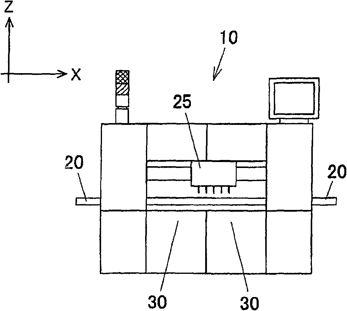
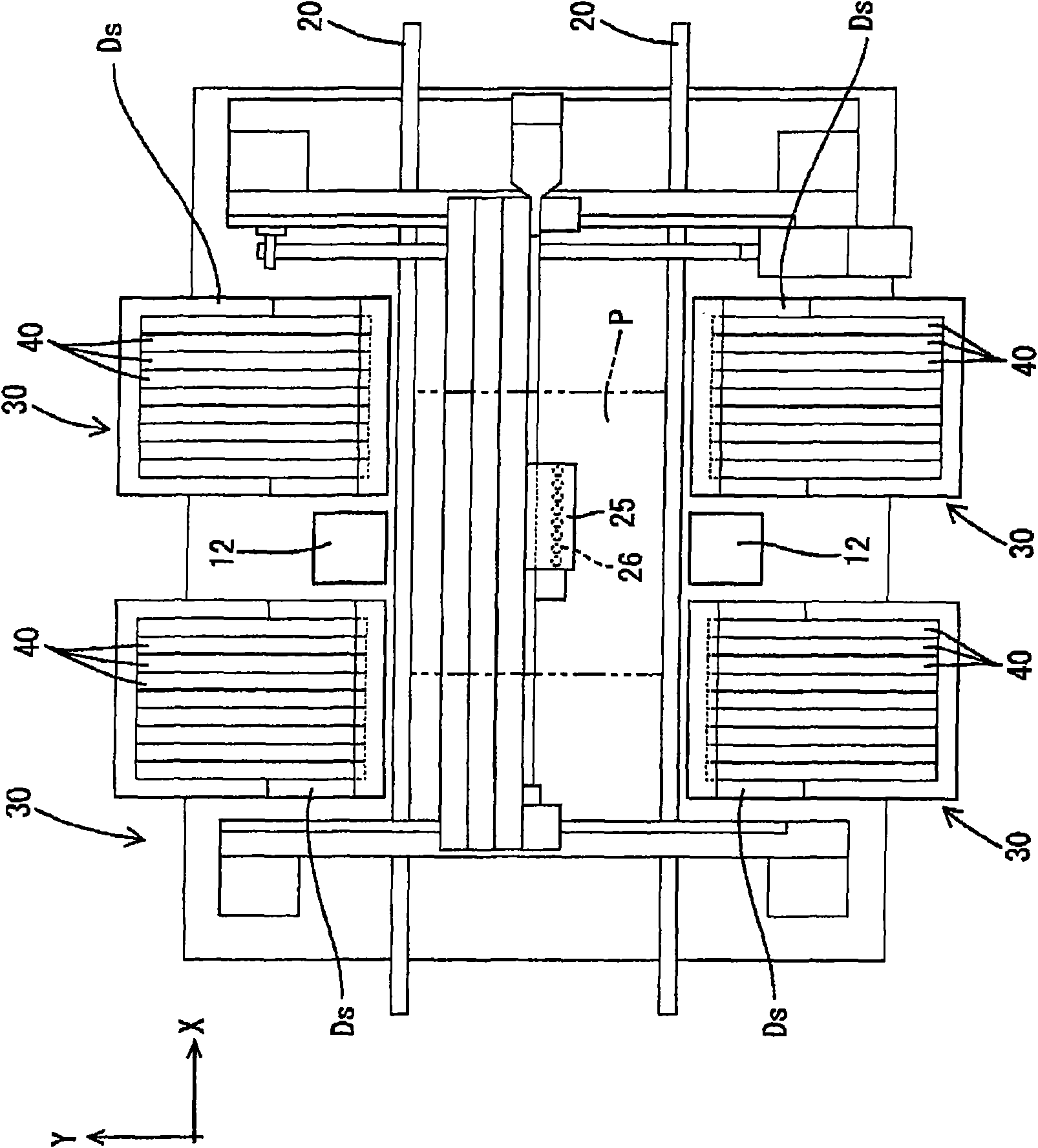
[0029] Such as figure 1 and figure 2 As shown, the surface mounter 10 includes a transfer device 20 for transferring a printed substrate P, component supply units 30 provided on both sides of the transfer device 20 , a head unit 25 , and the like.

[0030] The component supply unit 30 is configured by arranging a plurality of component supply devices 40 in a state of being positioned on a cart Ds, wherein the cart Ds is mounted on the surface in a state of being positioned in the X, Y, and Z directions. The main body of the mounting machine 10.

[0031] The head assembly 25 takes out components from the component supply unit 30 and sends them to the substrate P, and is movable in an area between the component supply unit 30 and the mounting position on the substrate P by driving a drive mechanism such as a servo motor.

[00...

no. 2 Embodiment approach

[0095] Next, a second embodiment will be described.

[0096] In the first embodiment, the component pressing portion 136 is provided on the tape guide 110 , but in the second embodiment, the component pressing portion 136 is eliminated. The shape of the tape guide 200 of the present embodiment is as follows: Figure 13 As shown, except for the element holding portion 136 , the shapes of other portions are the same as those of the first embodiment.

[0097] The element pressing part 136 is a part that restricts the stripping of the element after stripping. When there is no need to worry that the element will come out after stripping, it is also conceivable that the element pressing part 136 does not need to be provided or the element pressing part 136 is not provided. It is an appropriate case (for example, when destaticizing treatment is performed after peeling, etc.).

[0098] Therefore, for example, as long as the tape guide 110 of the first embodiment and the tape guide 2...

no. 3 Embodiment approach

[0101] Next, a third embodiment will be described.

[0102] In the first embodiment, the tape guide 110 is made of resin, but in the third embodiment, the tape guide is reinforced. The shape of the tape guide of this embodiment, such as Figure 14 As shown, the reinforcing plate 220 made of metal is bonded to the left and right side walls 215 of the main body 210 of the tape guide body 210 made of resin by bonding or integrally forming.


PUM


Abstract

It is intended to allow for readily performing a cover tape setting operation. In the present invention, a tape guide 110 for guiding a component supply tape 35 includes a front guide section 120 provided with an open surface 128 opened on one side thereof in a continuous manner in a tape feed direction, so as to allow a cover tape 37 to be taken in and out relative to the front guide section 120 through the open surface 128. This configuration makes it possible to perform the setting operation for the cover tape 37 through given operational steps, under a condition that the tape guide 110 remains fixed to a component supply unit 40.

Description

technical field [0001] The present invention relates to a component supply device for supplying components such as ICs using a tape as a carrier, and a surface mounter equipped with the component supply device. Background technique [0002] Conventionally, a tape feeder is known as one of devices for supplying components to a surface mounter. [0003] The tape feeder pulls the tape containing components at regular intervals from the reel and sends it to the component supply position in front of the feeder. A component supply tape as a carrier includes a carrier tape having a component accommodating portion, and a cover tape bonded to cover the component accommodating portion. The cover tape acts as a stopper so that the components do not come off until the component supply tape reaches the component supply position, and the cover tape is peeled off from the carrier tape near the component supply position. [0004] In the above-mentioned tape feeder, in order to supply comp...

Claims


Application Information

Patent Timeline
Patent Type & Authority Applications(China)
IPC IPC(8): H05K13/02
CPCH05K13/0452H05K13/0417Y10T29/53174Y10T29/53178Y10T29/49819Y10T29/53274H05K13/0419
Inventor 米光正典荒木治
Owner YAMAHA MOTOR CO LTD
Learn More