Improved steam drive oil production method

A technology of steam flooding and steam, which is applied in the direction of extraction fluid, earthwork drilling, wellbore/well components, etc., and can solve problems such as crude oil drive away

Active Publication Date: 2009-10-14
PETROCHINA CO LTD
View PDF2 Cites 14 Cited by
  • Summary
  • Abstract
  • Description
  • Claims
  • Application Information

AI Technical Summary

Problems solved by technology

However, due to gravity in the steam chamber, the crude oil is deposited in the lower part and the steam is in the upper part, so the crude oil cannot be driven away well

Method used


Image

  • Improved steam drive oil production method
  • Improved steam drive oil production method
  • Improved steam drive oil production method

Examples


Embodiment 1

[0037] Embodiment 1: Take the improved steam flooding oil recovery on an oil well after steam huff and puff as an example for illustration.

[0038] In an oil field, the depth of the oil layer is 800 meters, and the thickness of the oil layer is 20 meters. Steam huff and puff production has been carried out. After steam stimulation, the reservoir pressure was 2 MPa. A decision was made to develop improved steam flooding.

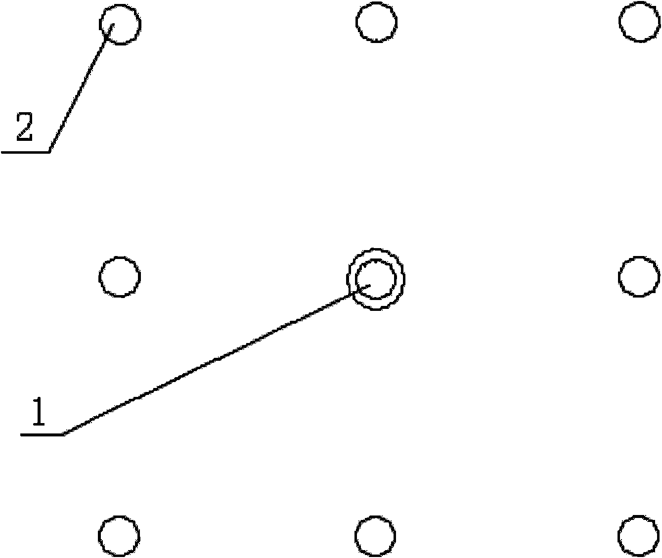
[0039] refer to image 3 . Step 1: Improve the well pattern in the steam area: use a nine-point well pattern, with the steam injection well 1 in the middle, surrounded by 8 production wells 2, and the 8 production wells 2 are arranged in a rectangle. The steam injection well 1 is 75 meters away from the closer production well 2, and 106 meters away from the farther production well 2. The steam injection well is connected with steam injection equipment, and the production well is connected with oil production equipment

[0040] refer to figure 1 . Step...

Embodiment 2

[0045] Embodiment 2: Take the improved steam flooding oil recovery on an oil well that has not undergone steam stimulation as an example to illustrate.

[0046] In an oil field, the depth of the oil layer is 800 meters, and the thickness of the oil layer is 20 meters. It has not been produced by steam huffing and puffing. The current reservoir pressure is 8 MPa. A decision was made to develop improved steam flooding.

[0047] refer to image 3 . Step 1: Improve the well pattern in the steam area: use a nine-point well pattern, with the steam injection well 1 in the middle, surrounded by 8 production wells 2, and the 8 production wells 2 are arranged in a rectangle. The steam injection well 1 is 75 meters away from the closer production well 2, and 106 meters away from the farther production well 2. The steam injection well is connected with steam injection equipment, and the production well is connected with oil production equipment

[0048] refer to figure 1 . Step 2: ...


PUM


Abstract

The invention relates to a steam drive oil production method which is applied to oil production in oil fields. The method comprises the following steps: enough steam amount is injected continuously in a steam injection well; under the condition of continuous injection of steam, peripheral production wells are opened for production and closed discontinuously; in the period of closing the well, the pressure of an oil pool at the periphery of the steam injection well raises, and when the pressure raises to a certain extent, the production wells are opened for production; with the opening of the production wells, the pressure of the oil pool at the periphery of the steam injection well decreases, and when the pressure decreases to a certain extent, the production wells are closed; the above steps are repeatedly circulated; when the pressure raises, the saturation temperature of the steam can raise, the heat can be transferred to the rock and crude oil of the reservoir and the temperature of the rock and the crude oil in the reservoir can also raise; when the pressure decreases, the saturation temperature of the steam can decrease, and when the pressure of the rock and the crude oil in the reservoir raises, the temperature formed is higher than the saturation temperature of the steam; and part of water contained in the crude oil and on the surface of the rock is flash-evaporated into steam so as to form foam oil which displaces the crude oil.

Description

technical field [0001] The invention relates to the technical field of oil recovery in oil fields, in particular to a method for producing crude oil by steam flooding, which improves the recovery rate and development effect of oil reservoirs. Background technique [0002] The conventional steam flooding technology is to continuously inject steam from the steam injection well into the heavy oil reservoir, use the heat carried by the steam to heat the heavy oil and the oil layer, and form a steam cavity. The viscosity of the crude oil in the steam cavity is reduced and the fluidity is improved. The steam is driven to the production wells around the steam injection well, and the production wells are continuously producing. However, due to gravity in the steam chamber, the crude oil is deposited in the lower part and the steam is in the upper part, so the crude oil cannot be driven away well. [0003] Patent Publication No.: CN1385595A, provides a method of enhanced oil recover...

Claims


Application Information

Patent Timeline
Patent Type & Authority Applications(China)
IPC IPC(8): E21B43/24
Inventor 陈亚平
Owner PETROCHINA CO LTD
Why Eureka
Try Eureka