Bar magnet

A magnetic bar and pole technology, applied in the manufacture of magnets, magnetic objects, inductors/transformers/magnets, etc., can solve the problems of easy rotation of the magnetic bar, affecting the magnetic field strength, and difficulty in distinguishing

Inactive Publication Date: 2009-10-14
邵天君
View PDF0 Cites 0 Cited by
  • Summary
  • Abstract
  • Description
  • Claims
  • Application Information

AI Technical Summary

Problems solved by technology

[0002] In order to meet the needs of use, multiple magnetic rods are often used to interact to enhance the magnetic field. It is usually necessary to identify different magnetic poles and their dividing lines. Most of the currently used magnetic rods are divided into N and S along the cross section of the magnetic rod. Two magnetic poles, but sometimes it is necessary to use a large area of ​​strong magnetic field, so people manufacture magnetic rods that are divided into N and S different magnetic poles along the longitudinal direction. No matter which of the above magnetic rods, it is not easy to distinguish which part is N intuitively Pole, which part is S, which brings a lot of inconvenience to use
The factory usually uses different colors on the surface of the magnetic rods to distinguish them when leaving the factory, but over time, the colors tend to fall off and cannot be clearly distinguished, and fine particles are prone to appear during the color falling off process, resulting in more negative effects
[0003] For cylindrical magnetic rods, it is difficult to locate effectively during the interaction of multiple magnetic rods, and the magnetic rods are easy to rotate, which affects the magnetic field strength

Method used


Image

  • Bar magnet
  • Bar magnet
  • Bar magnet

Examples


Embodiment

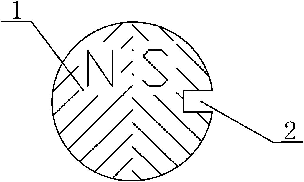
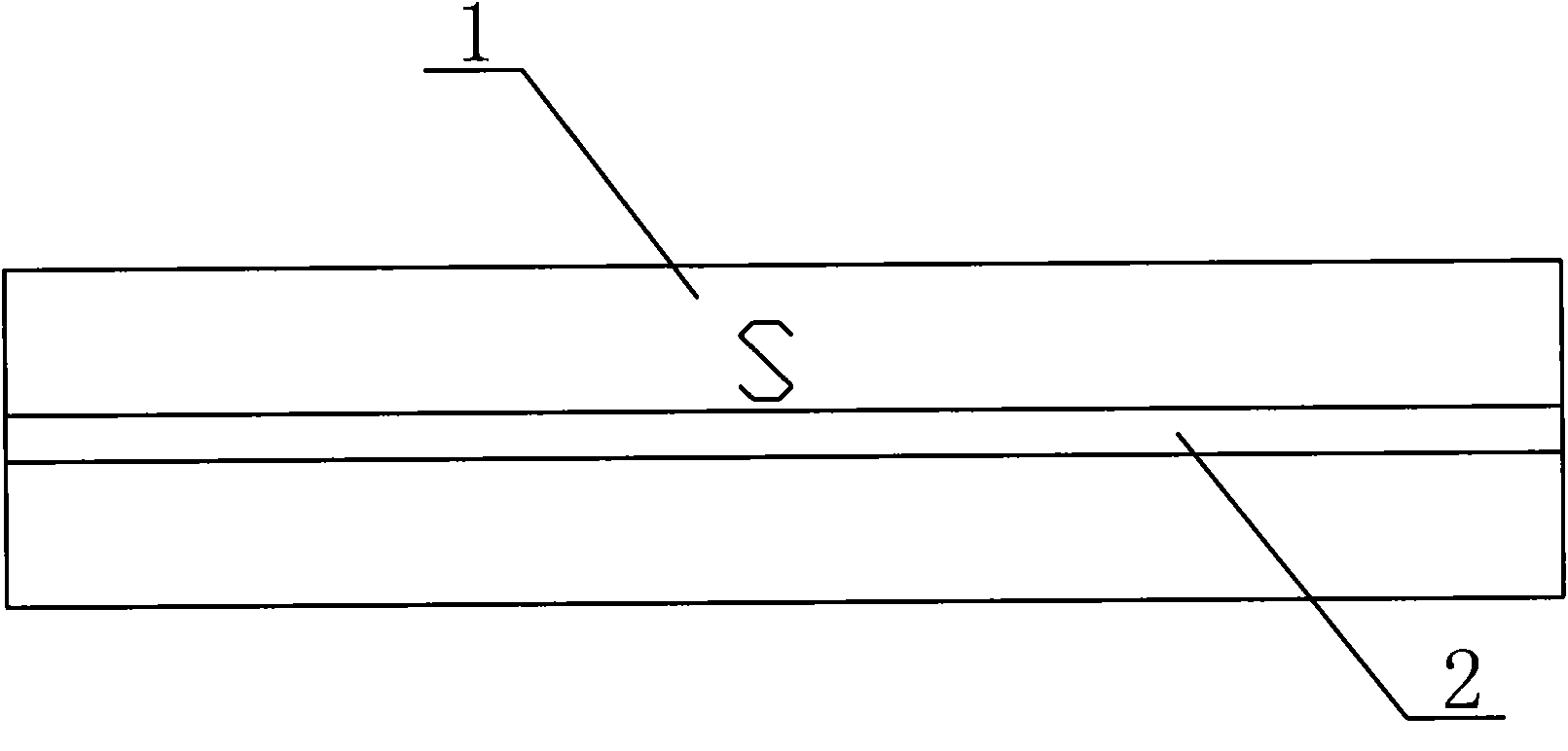
[0018] A magnetic rod according to the present invention. The magnetic rod 1 is cylindrical and includes two halves with different magnetic poles of N and S in the longitudinal direction, such as figure 2 As shown, only the S pole part of the magnet bar 1 is provided with a groove 2 passing through the arc-shaped surface of the magnet bar along the longitudinal direction; figure 1 Said, the groove 2 is centrally symmetrically arranged on the vertical line of the dividing line of the different magnetic poles of N and S. Therefore, it is possible to clearly know which regions are N poles and which regions are S poles. You have to find the dividing line of different magnetic poles.

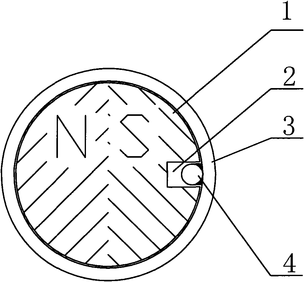
[0019] Such as image 3 As shown, when in use, the magnetic rod 1 is set in a circular sleeve 3, and the circular sleeve 3 is provided with a pin 4 that matches the groove 2 of the magnetic rod. In this way, the magnetic rod 1 is restricted. .

Embodiment 2

[0021] Such as Figure 4 The magnet bar 1'shown is a regular hexagonal prism, which is divided into N and S poles on the left and right. A blind hole 2'is longitudinally provided on the vertical line of the boundary line of different magnetic poles on the S extreme face.


PUM


Abstract

The invention relates to a bar magnet. The bar magnet comprises a longitudinal left half body and a longitudinal right half body which have different magnetic poles, and the bar magnet is longitudinally provided with a mark; on the cross section of the bar magnet, the center of the mark is located on a perpendicular bisector of a dividing line of different magnetic poles and deviates from a center point of the cross section of the bar magnet. The bar magnet helps easily identify different magnetic poles, and has the advantages of convenient location and use.

Description

Technical field [0001] The invention relates to a magnetic rod. Background technique [0002] In order to meet the needs of use, multiple magnetic rods are often used to interact to enhance the magnetic field. It is usually necessary to distinguish different magnetic poles and their dividing lines. Most of the currently used magnetic rods are divided into N and S along the cross section of the magnetic rod. There are two magnetic poles, but sometimes a large area of ​​strong magnetic field is needed. Therefore, people have made magnetic bars that are divided into N and S magnetic poles along the longitudinal direction. No matter which kind of magnetic bar is mentioned above, it is not easy to distinguish which part is N. Extremely, which part is S, brings a lot of inconvenience to use. When leaving the factory, the factory usually paints different colors on the surface of the magnetic bar to show distinction, but after a long time, the color is easy to fall off and cannot be clea...

Claims


Application Information

Patent Timeline
IPC IPC(8): H01F7/00H01F41/02
Inventor 邵天君
Owner 邵天君
Why Eureka
Try Eureka