
Motor

A technology of motors and bearings, applied in the direction of casing/housing/support, controlling mechanical energy, manufacturing stator/rotor body, etc.

Inactive Publication Date: 2009-10-14
SUNONWEALTH ELECTRIC MACHINE IND
View PDF0 Cites 4 Cited by
  • Summary
  • Abstract
  • Description
  • Claims
  • Application Information

AI Technical Summary

Problems solved by technology

[0008] The present invention provides a motor, which is used to solve many problems caused by the buckle of the existing motor easily rotating with the mandrel, which is the main purpose of the invention

Method used


Image

  • Motor
  • Motor
  • Motor

Examples


Embodiment Construction

[0044] In order to make the above-mentioned and other objects, features and advantages of the present invention more comprehensible, the preferred embodiments of the present invention are specifically cited below, together with the accompanying drawings, as follows:

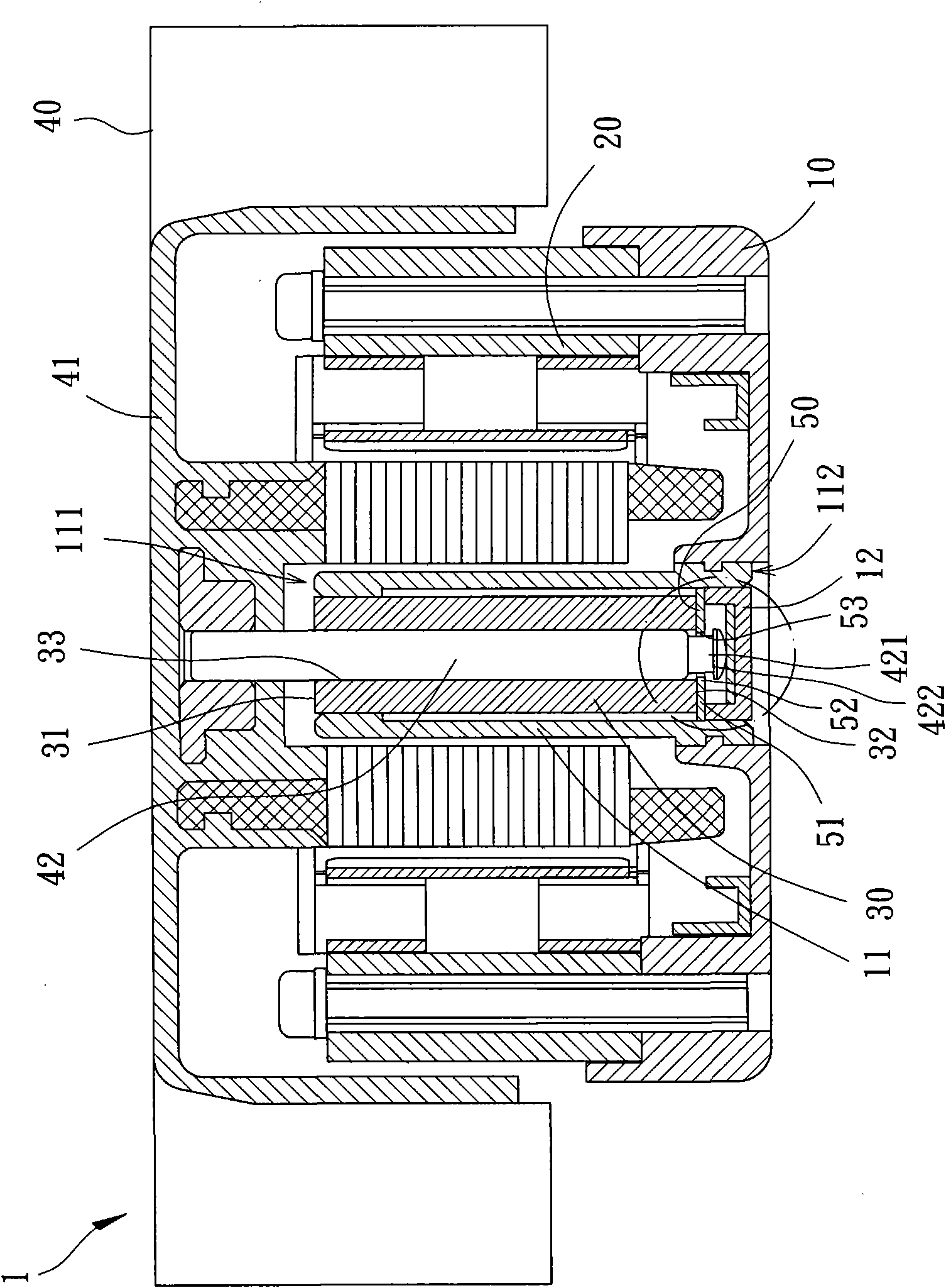
[0045] Please refer to image 3 and 4 As shown, the motor 1 of the first embodiment of the present invention includes a base 10 , a stator 20 , a bearing 30 , a rotor 40 and a retaining ring 50 .

[0046] The base 10 is provided with a shaft tube 11, the shaft tube 11 has a first end 111 and a second end 112, the first end 111 forms an open shape, and the second end 112 forms a closed shape; wherein, the The shaft tube 11 can be a hollow shaft tube with openings formed at both ends, and then a center cap 12 is placed at the second end 112 to close the second end of the shaft tube 11; or, the shaft tube 11 The second end 112 can also be directly formed into a closed shape by integral molding.

[0047] The stator ...


PUM


Abstract

The invention discloses a motor which comprises a base, a stator, a bearing, a rotor and a retaining ring; the base is provided to combine the stator and the bearing; the stator is provided with a core shaft on which a retaining groove and a clamping part are arranged; the retaining groove and the clamping part are respectively provided with a first external diameter and a second external diameter; the second external diameter is larger than the first external diameter; the retaining ring is held by the retaining groove and is provided with a combining part and a holding part; the combining part can be used for positioning the retaining ring and the holding part surrounds to form an inner hole; the diameter of the inner hole is larger than the first external diameter and smaller than the second external diameter so that a gap exists between the inner hole and the clamping groove, thereby preventing noise generated by the friction between the retaining ring and the core shaft, ensuring that the stator never falls off the base arbitrarily and avoiding excessive restriction in assembly.

Description

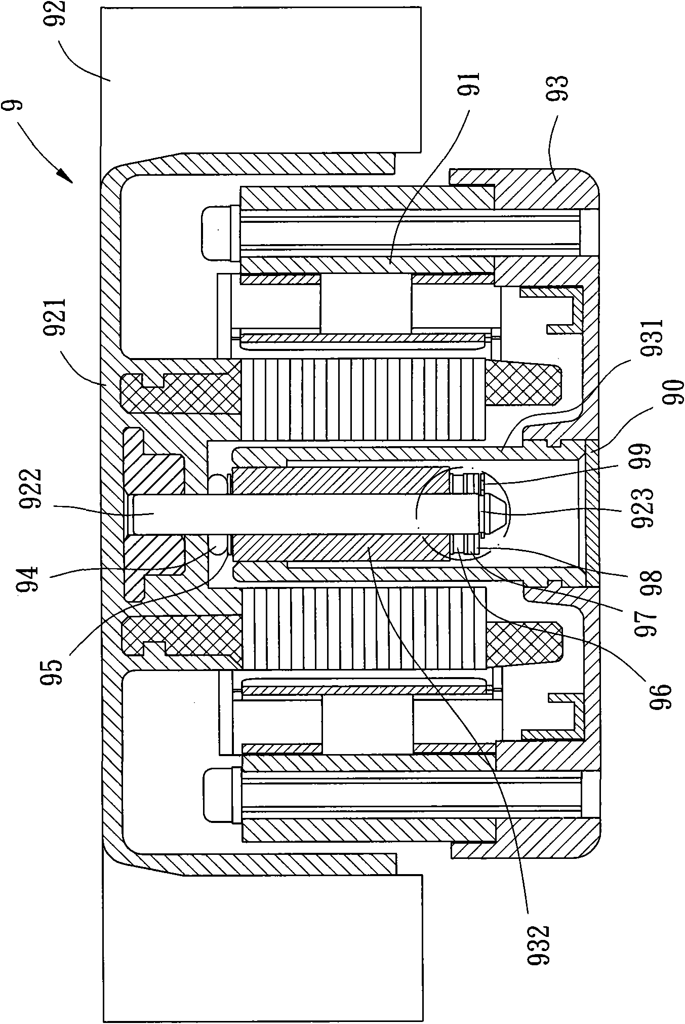
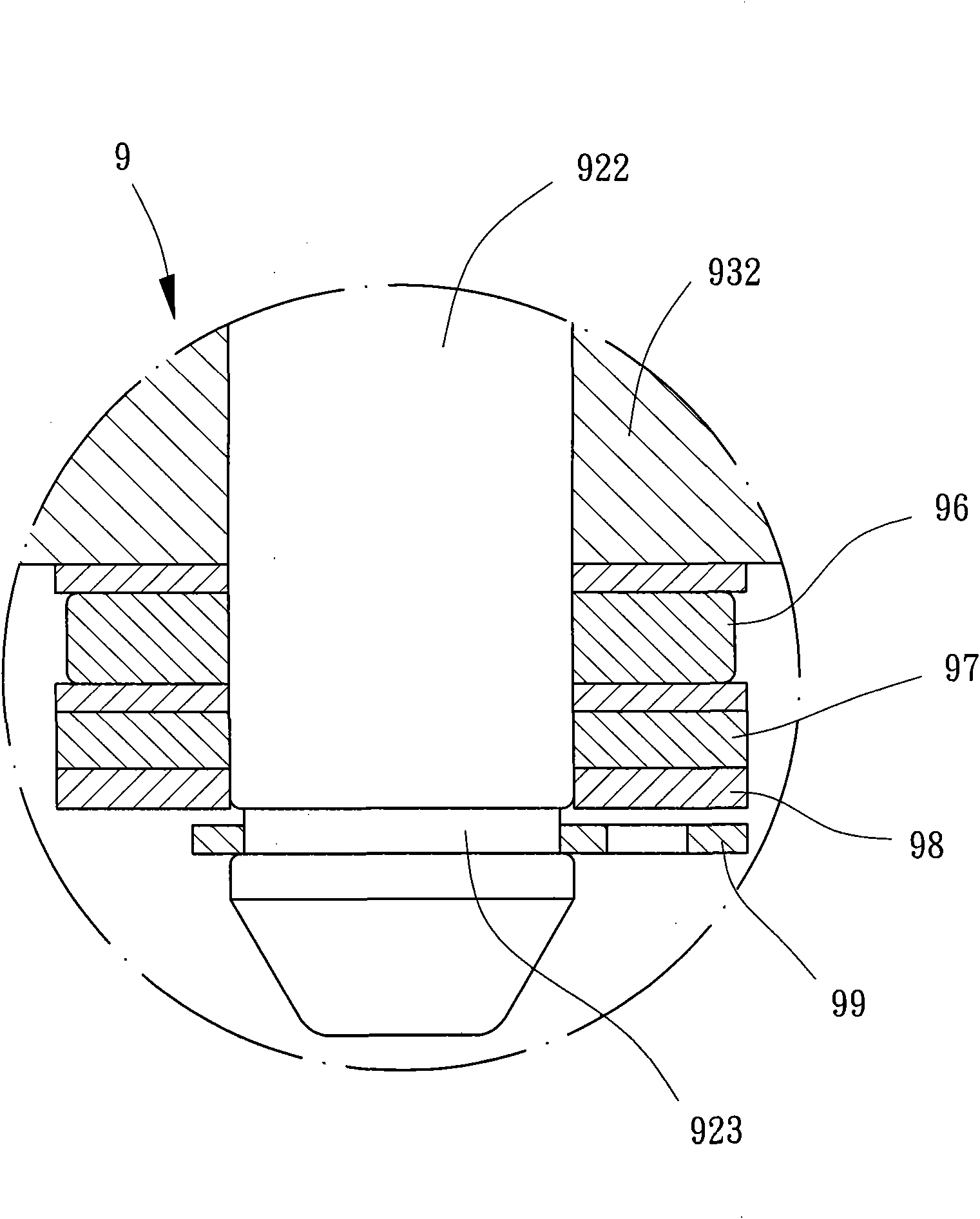
technical field [0001] The invention relates to a motor structure, in particular to a motor capable of effectively preventing the buckle from shifting in the shaft tube and avoiding the friction noise caused by the buckle. Background technique [0002] Please refer to figure 1 As shown, the conventional motor 9 generally includes a stator 91 and a rotor 92 . The stator 91 is installed and fixed on a shaft tube base 93, and a shaft tube 931 is fixed in the center of the shaft tube base 93, and a bearing 932 is disposed inside the shaft tube 931, and the bearing 932 is provided with a shaft hole (not shown). [0003] The rotor 92 has a hub 921, the center of the hub 921 is provided with a mandrel 922, and the end of the mandrel 922 is provided with a buckle groove 923; Mylar (Mylar polyester film sheet) 95 etc. components, can wear the axis hole of this bearing 932; After components such as (mylar) 97 and Washer 98 (washer spring pad), combine a buckle 99 in the buckle groo...

Claims


Application Information

Patent Timeline
IPC IPC(8): H02K7/08H02K5/16H02K15/02
Inventor 洪银树
Owner SUNONWEALTH ELECTRIC MACHINE IND
Learn More