Method for controlling illuminative high-power LED
A control method and high-power technology, applied in the field of high-power LED control for lighting, can solve the problem that the electrical parameters and temperature coefficients of LED integrated circuits are not completely consistent, restrict the popularization and application of high-power LED integrated circuits, and individual or partial integrated circuits are burned out. and other problems, to achieve the effect of extensive industrial utilization value, control method or function improvement, stability and service life improvement
- Summary
- Abstract
- Description
- Claims
- Application Information
AI Technical Summary
Problems solved by technology
Method used
Image
Examples
Embodiment 1
[0022] Simpler, the present invention can use circuit elements such as resistors and resistance-capacitance networks to form a classic current sharing circuit. When the current flowing through a certain LED monomer group increases and is greater than other LED monomer groups, the current sharing circuit The current also increases, and the voltage at both ends of the current equalizing circuit increases, forcing the current of the LED monomer group to be distributed to other LED monomer groups, so as to achieve the effect of evenly distributing the current among the LED monomer groups.
Embodiment 2
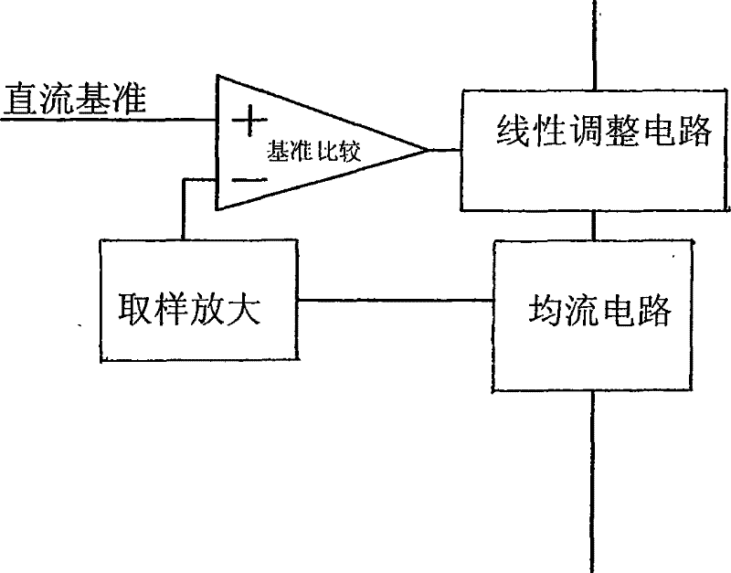
[0024] see figure 1 As shown, the present invention can also be improved on the basis of Embodiment 1, and is realized through the following steps:
[0025] Step 1, setting the reference signal;
[0026] Step 2: Sampling and amplifying the circuit parameters of each LED monomer group to obtain a sampled and amplified signal;
[0027] Step 3, comparing the sampled amplified signal with the reference signal;
[0028] Step 4, when the sampled and amplified signal of a certain LED monomer group deviates from the reference signal, the current of the LED monomer group is adjusted.
[0029] Step five, when the current of one LED monomer group is greater than that of other LED monomer groups, distribute the current to other LED monomer groups.
[0030] The sampling of the above-mentioned step 2 and the step 5 can be realized simultaneously through a current sharing circuit composed of a resistor or a resistance-capacitance network, and the current sharing circuit, amplification cir...
Embodiment 3
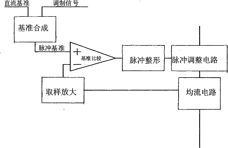
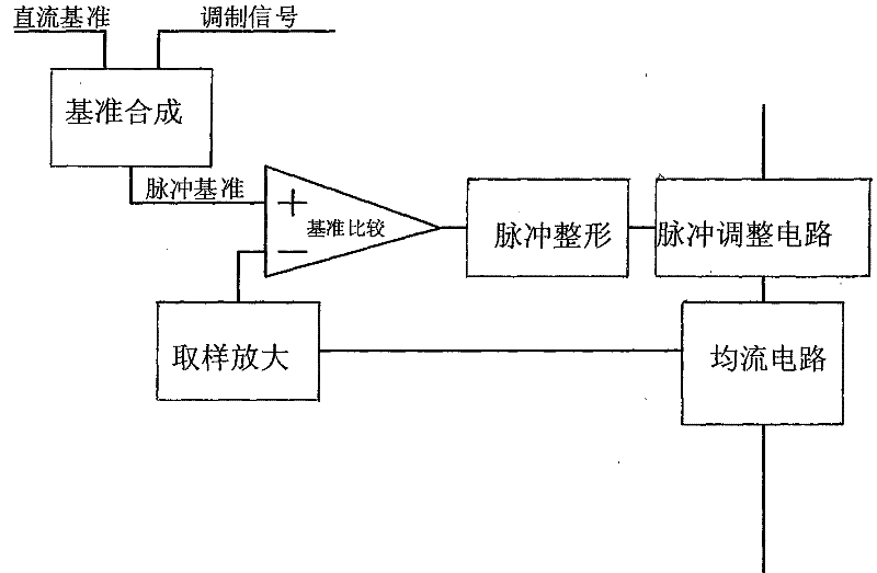
[0033] see figure 2 Shown, the present invention can also be realized through the following steps:
[0034] Step 1, setting reference parameters, generating a modulation signal, and superimposing the reference parameters and the modulation signal to synthesize a pulse reference signal;
[0035] Step 2: Sampling and amplifying the circuit parameters of each LED monomer group to obtain a sampled and amplified signal;
[0036] Step 3, comparing the sampled amplified signal with the pulse reference signal to obtain a PWM pulse signal;
[0037] Step 4, when the PWM pulse signal shows that the sampled and amplified signal of a certain LED monomer group deviates from the pulse reference signal, the current of the LED monomer group is adjusted.
[0038] Step five, when the current of one LED monomer group is greater than that of other LED monomer groups, distribute the current to other LED monomer groups.
[0039] Preferably, the sampling in step 2 and step 5 can be realized simul...
PUM
 Abstract
Description
Claims
Application Information
 - R&D
- Intellectual Property
- Life Sciences
- Materials
- Tech Scout
- Unparalleled Data Quality
- Higher Quality Content
- 60% Fewer Hallucinations
Browse by: Latest US Patents, China's latest patents, Technical Efficacy Thesaurus, Application Domain, Technology Topic, Popular Technical Reports.
© 2025 PatSnap. All rights reserved.Legal|Privacy policy|Modern Slavery Act Transparency Statement|Sitemap|About US| Contact US: help@patsnap.com


