Supercharge Your Innovation With Domain-Expert AI Agents!

Cell cover locking structure

A battery cover and lock technology, which is applied to the structure of the telephone, structural parts, battery pack parts, etc., can solve the problems of battery cover 12 detachment, troublesome operation of battery cover 12 separation, loss, etc.

Inactive Publication Date: 2009-10-28
SHENZHEN FUTAIHONG PRECISION IND CO LTD
View PDF0 Cites 9 Cited by
  • Summary
  • Abstract
  • Description
  • Claims
  • Application Information

AI Technical Summary

Problems solved by technology

[0004] However, the battery cover 12 of the battery cover locking structure 10 is relatively thin and closely attached to the body 11, so the separation operation of the battery cover 12 from the body 11 is very troublesome, thus causing inconvenience in battery replacement.
In addition, after the battery cover 12 is completely separated from the body 11, the battery cover 12 needs to be kept separately, and when the portable electronic device falls, the battery cover 12 is easily separated from the body 11 and lost.

Method used


Image

  • Cell cover locking structure
  • Cell cover locking structure
  • Cell cover locking structure

Examples


Embodiment Construction

[0015] The invention discloses a locking structure of a battery cover, which is suitable for portable electronic devices such as mobile phones. In this embodiment, a mobile phone is taken as an example for illustration.

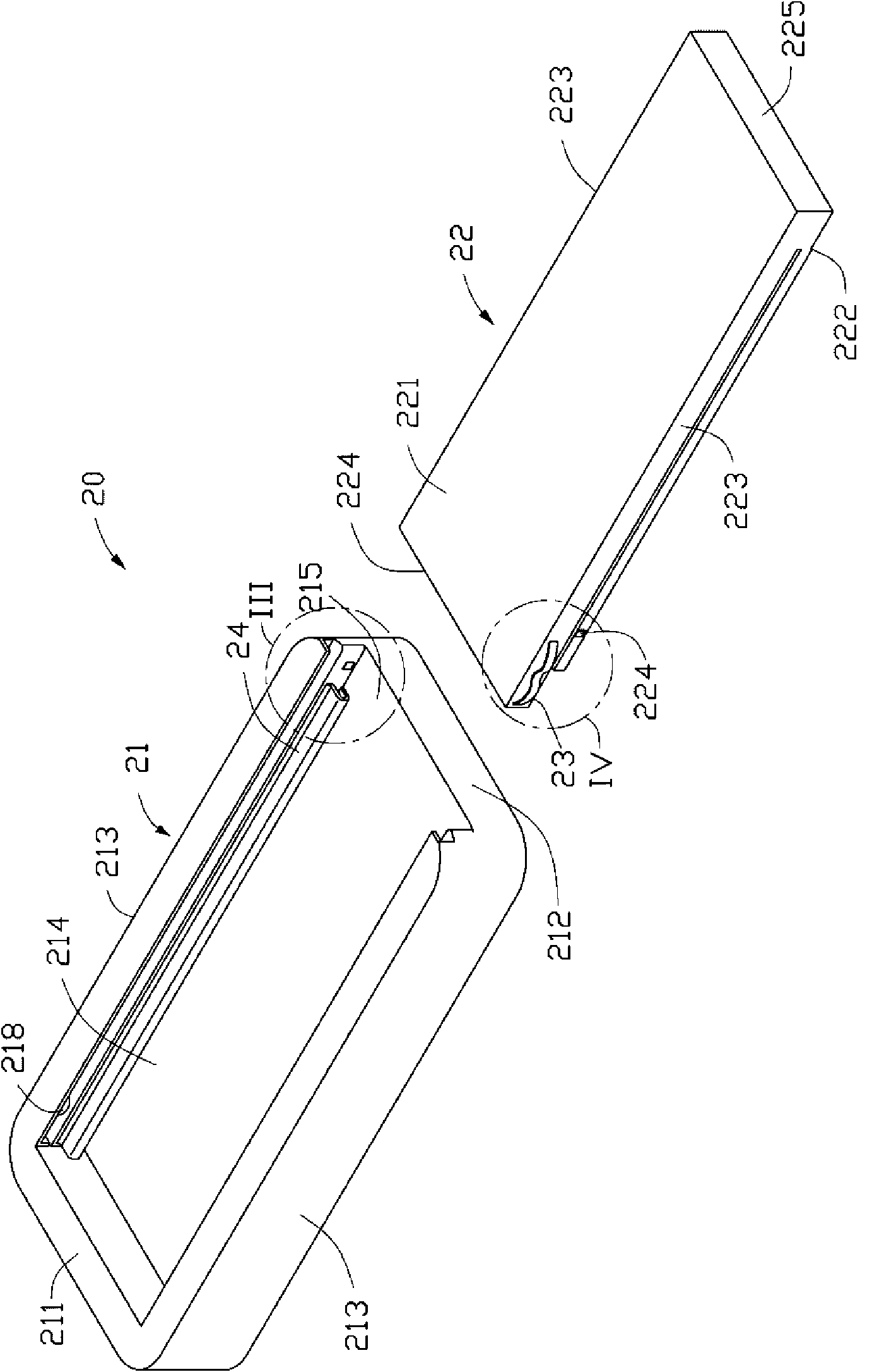
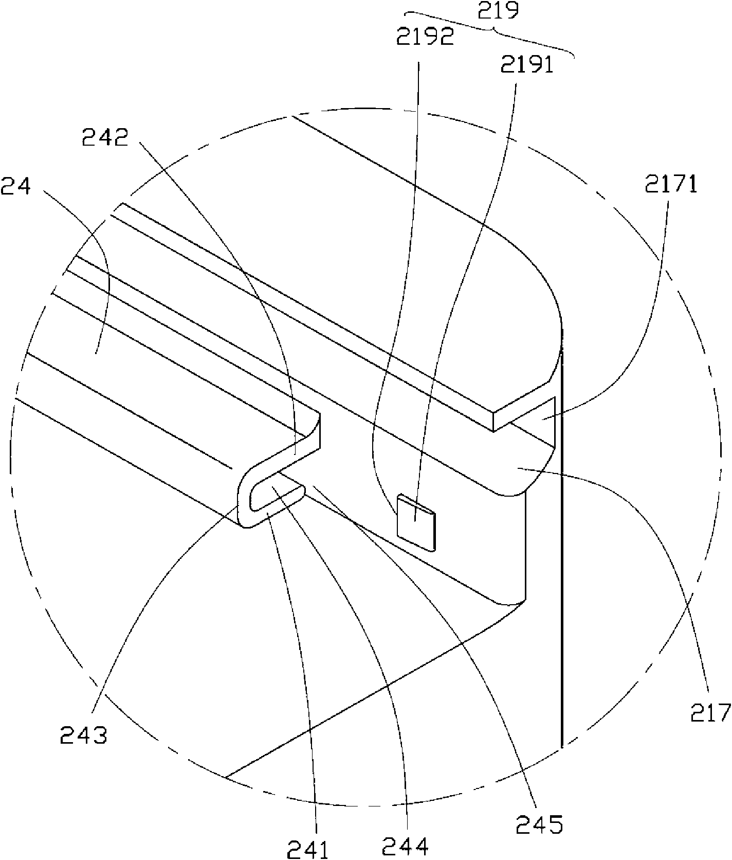
[0016] see Figure 2 to Figure 5 , The battery cover locking structure 20 of the present invention includes a body 21 , a battery cover 22 , two elastic members 23 , two first guide rails 24 and two second guide rails 25 . The elastic member 23 is fixed on the battery cover 22 . The first guide rail 24 is fixed on the body 21 . The second guide rail 25 is fixed on the battery cover 22 . Through cooperation of the first guide rail 24 and the second guide rail 25 , the battery cover 22 is slidably covered on the body 21 .

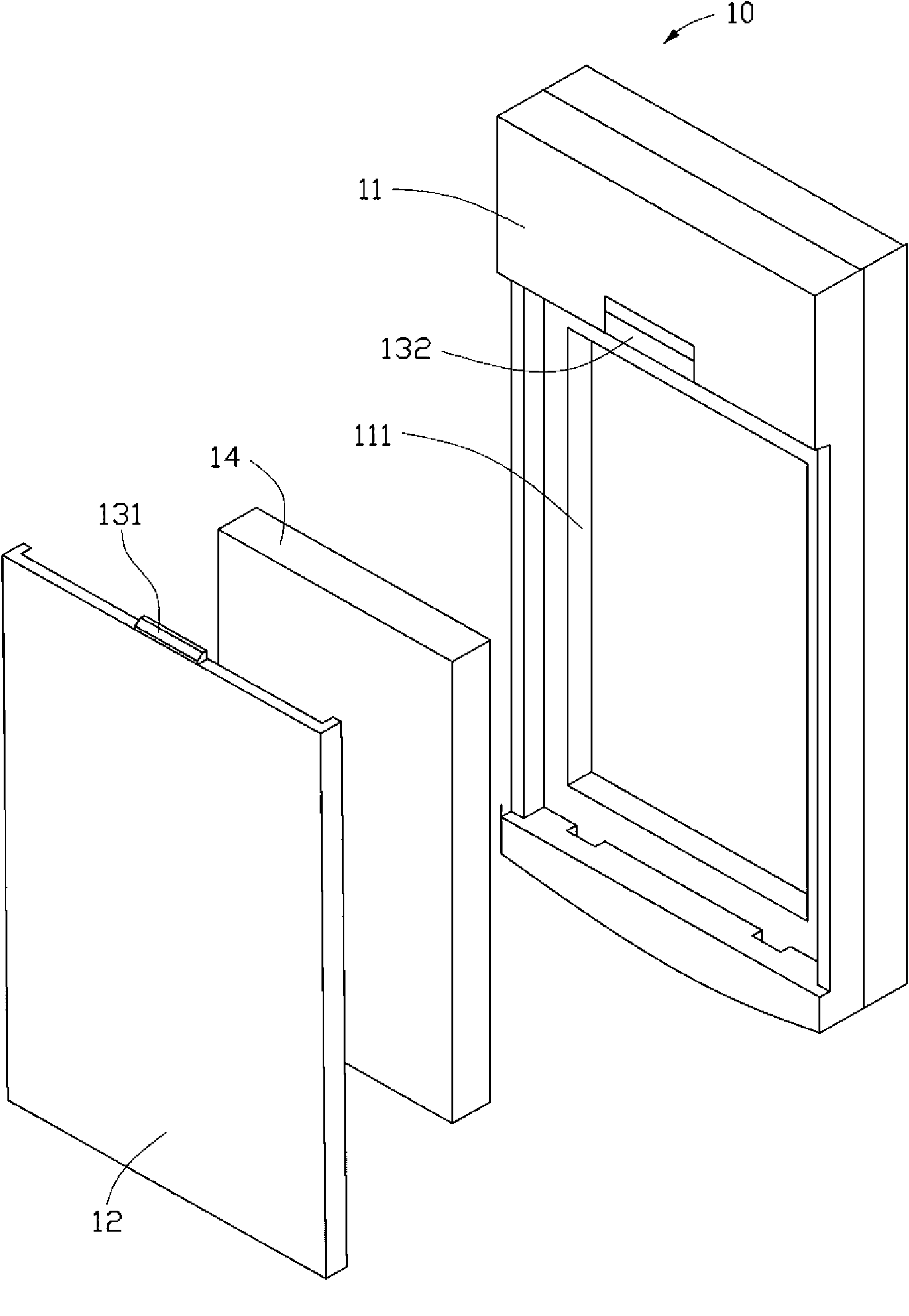
[0017] The body 21 has a top wall 211 , a bottom wall 212 opposite to the top wall 211 , and two side walls 213 connecting the top wall 211 and the bottom wall 212 . The top wall 211, the bottom wall 212 and the two side walls 213 encirc...


PUM


Abstract

The invention provides a cell cover locking structure, which comprises a machine body, a separation preventing device and a cell cover capable of covering the machine body in a sliding mode. The separation preventing device comprises a first separation preventing piece and a second separation preventing piece; the first separation preventing piece is arranged on the machine body; the second separation preventing piece is arranged on the cell cover; and the first separation preventing piece is matched with the second separation preventing piece, so that the cell cover is undetachably arranged on the machine body in a sliding mode.

Description

technical field [0001] The invention relates to a locking structure of a battery cover, in particular to a locking structure of a battery cover applied to portable electronic devices such as mobile phones. Background technique [0002] Mobile phones and personal digital assistants (Personal Digital Assistant, PDA) and other portable electronic devices are increasingly widely used, and the batteries that provide energy for portable electronic devices have to be replaced due to energy consumption. In order to make the battery easy to install, people have designed Many battery cover snap-lock structures. [0003] see figure 1 , an existing battery cover locking structure 10 of a portable electronic device includes a body 11, a battery cover 12 and a fixing device. The body 11 defines a battery receiving slot 111 for accommodating a battery 14 therein. The fixing device includes a locking block 131 formed on the upper side of the battery cover 12 and a locking slot 132 formed...

Claims


Application Information

Patent Timeline
Patent Type & Authority Applications(China)
IPC IPC(8): H01M2/10H05K5/03H05K7/00H04M1/02G06F1/16H01M50/247H01M50/262
CPCY02E60/12H01M2/1066Y02E60/10H01M50/209
Inventor 施政张智强
Owner SHENZHEN FUTAIHONG PRECISION IND CO LTD
Features
  • R&D
  • Intellectual Property
  • Life Sciences
  • Materials
  • Tech Scout
  • Unparalleled Data Quality
  • Higher Quality Content
  • 60% Fewer Hallucinations
Learn More