Valve assembly of machine for generating high speed phase change ink image

A technology of phase change ink and image generation, which is applied to the electrical recording process using charge graphics, equipment and instruments using the electrical recording process using charge graphics, and can solve the problem of limiting the printing speed of machines 10, slow response time storage and control systems Throughput speed, slow closing rate and other issues, to achieve the effect of improving the opening time

Inactive Publication Date: 2013-09-25
XEROX CORP
View PDF7 Cites 0 Cited by
  • Summary
  • Abstract
  • Description
  • Claims
  • Application Information

AI Technical Summary

Problems solved by technology

The slow reaction time of the passive ball valve limits the throughput speed of the storage and control system 400 and thus the printing speed of the machine 10
Also, slow closure rates allow more ink to leak through the ball valve before sealing, which in turn leads to reduced system performance

Method used


Image

  • Valve assembly of machine for generating high speed phase change ink image
  • Valve assembly of machine for generating high speed phase change ink image
  • Valve assembly of machine for generating high speed phase change ink image

Examples


Embodiment Construction

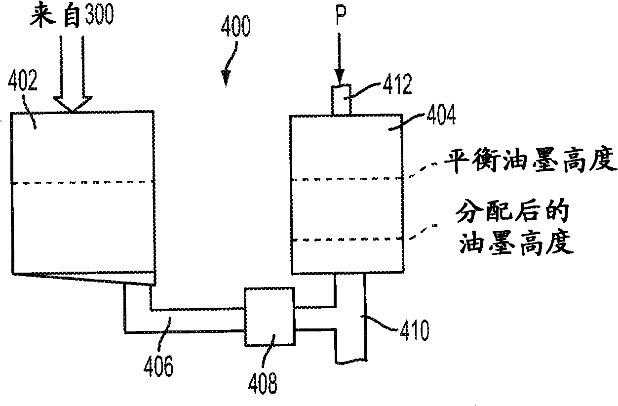
[0026] According to one embodiment, the molten liquid ink storage and control assembly 400 includes a valve assembly 408 incorporating a passive valve disc 420, such as Figure 4 to Figure 5 shown. The valve disc 420 is located in a valve chamber 421 defined by the valve housing 409 which is in fluid communication at the outlet 405 of the secondary reservoir 404 and to the primary reservoir ( image 3 ) between conduits or pipes 406. exist Figure 4 In the orientation shown in solid lines, valve disk 420 is in its "open" position, allowing liquid ink to flow from the primary reservoir to the secondary reservoir. As mentioned above, this open position allows the horizontal or vertical flow of liquid ink between the two reservoirs to equalize due to the difference in pressure head.

[0027] In one embodiment, the valve housing 409 includes an insert 432 disposed in the valve chamber 421 configured to direct liquid ink from The secondary storage flows to outlet 410, as descri...


PUM


Abstract

A valve assembly is provided for a high-speed phase change ink image producing machine between a first storage reservoir for receiving and holding a first volume of melted ink from a source and a second storage reservoir for holding a second volume of melted ink to be delivered under pressure to a printhead system. The valve assembly includes a passive valve disc movable from the closed position in which said disc abuts a valve seat in sealed contact, and an open position in which said valve disc is supported by an angled surface. An upper portion of the valve disc is unsupported and a flow director surface behind the disc directs fluid flow against the upper portion to assist in closing the valve. The surface characteristics of the valve seat are controlled to improve the "crack" time of the valve disc when opening.

Description

technical field [0001] The present invention relates to image generating machines, and in particular to solid ink machines using phase change ink melting and control devices. Background technique [0002] In general, phase-change ink image-generating machines, such as printers, use phase-change inks that are in a solid phase at ambient temperatures, but at the elevated operating temperatures of the machine or printer, a molten or molten liquid phase exists (and can act as droplets. spray or spray jet). At such elevated operating temperatures, droplets or jets of molten or liquid phase change ink are ejected from the printhead assembly of the printer onto the print media. Such spraying may be directed onto the final image receiving substrate, or indirectly onto the imaging member prior to transfer from it to the final image receiving medium. In either case, when the ink droplets contact the surface of the print medium, they rapidly solidify to form a predetermined pattern o...

Claims


Application Information

Patent Timeline
Patent Type & Authority Patents(China)
IPC IPC(8): B41J2/005B41J2/175
CPCG03G15/01B41J2/17593G03G2215/0187B41J2/17596
Inventor I·麦克雷肯L·E·欣德曼S·L·埃斯特格林
Owner XEROX CORP
Why Eureka
Try Eureka