Solenoid valve with improved opening and closing characteristics

A technology of solenoid valves and closing elements, which is applied in the field of solenoid valves, can solve problems such as poor closing time, and achieve the effect of simple cost

Active Publication Date: 2019-03-08
ROBERT BOSCH GMBH
View PDF4 Cites 0 Cited by
  • Summary
  • Abstract
  • Description
  • Claims
  • Application Information

AI Technical Summary

Problems solved by technology

However, the turn-off time is worse due to the separation of the magnetic loops

Method used


Image

  • Solenoid valve with improved opening and closing characteristics
  • Solenoid valve with improved opening and closing characteristics
  • Solenoid valve with improved opening and closing characteristics

Examples


Embodiment Construction

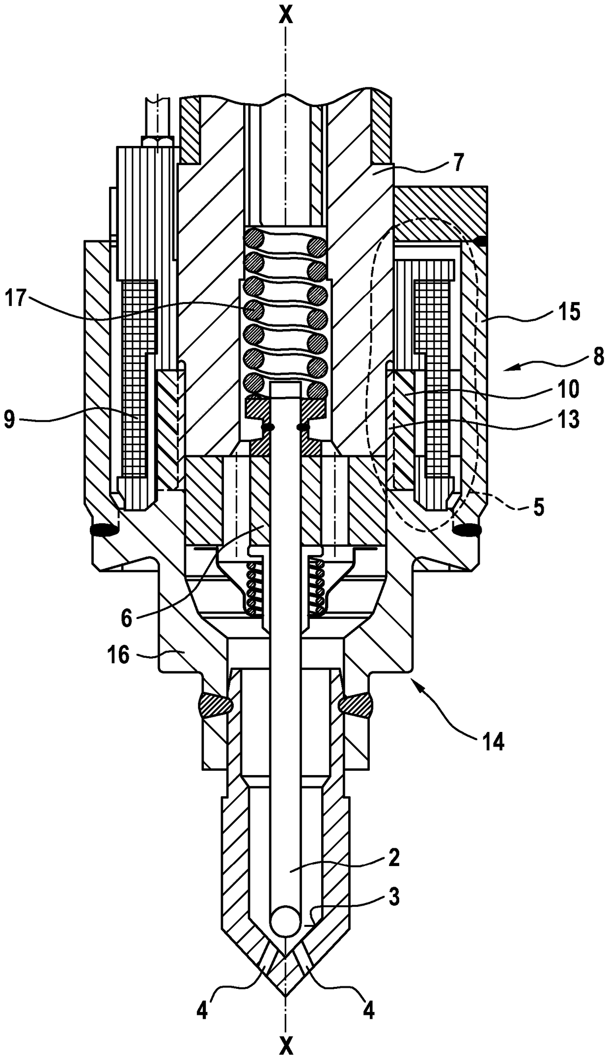
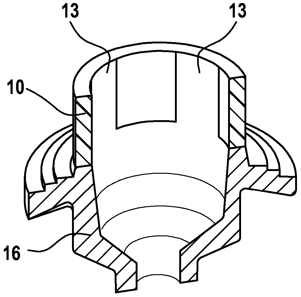
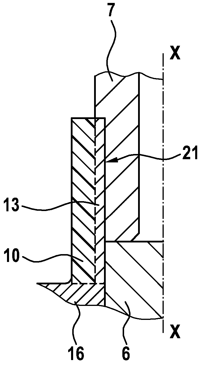
[0016] Refer to the attached Figures 1 to 3 The solenoid valve 1 for controlling fluid according to the first embodiment will be described in detail.

[0017] as from figure 1 Obviously, the solenoid valve 1 comprises a closing element 2 in the form of a valve needle, which has a ball on the closing side, which releases and closes the outlet opening 4 on the valve seat 3 .

[0018] Furthermore, the solenoid valve 1 includes a magnetic circuit 5 with an armature 6 , an inner pole 7 and a yoke 8 . In this exemplary embodiment, the magnetic yoke 8 is part of the housing 14 of the solenoid valve, the housing 14 being constructed in multiple parts. Here, the two housing parts 15 , 16 are part of the magnetic circuit 5 .

[0019] Furthermore, solenoid valve 1 includes a coil 9 which attracts armature 6 when energized. After the coil 9 has ended the current flow, the restoring element 17 returns the armature 6 to the starting position again. here, figure 1 The open state of th...


PUM


Abstract

The invention relates to a solenoid valve for controlling a fluid, comprising: a closing element (2) which releases and closes at least one discharge opening (4) on a valve seat (3); a magnetic circuit (5) , which has an armature (6), an inner pole (7) and a yoke (8); and a coil (9), wherein the armature (6) is connected to the closing element (2), wherein the magnetic ring The circuit (5) comprises a non-magnetic separating element (10) for interrupting the magnetic circuit (5), and wherein at least one of the valves is arranged on the non-magnetic separating element (10) A magnetic connecting piece (13; 23) extending in the axial direction (X-X) of the .

Description

technical field [0001] The invention relates to a solenoid valve for controlling fluids, in particular fuel, which has improved opening characteristics and at the same time also improved closing characteristics. Background technique [0002] Solenoid valves are known in various designs from the prior art, for example as injection valves. It has been found that a solenoid injection valve with a non-magnetic separation, ie a non-magnetic region, in the region of the armature in the housing opens faster under the same conditions than a valve of this type without a magnetic circuit. However, the closing time is worse due to the separation of the magnetic loops. Contents of the invention [0003] In contrast, the solenoid valve according to the invention for controlling a fluid has the advantage that both the opening time and the closing time of the solenoid valve can be improved and, in particular, can be produced particularly simply and cost-effectively. The electromagnetic...

Claims


Application Information

Patent Timeline
Patent Type & Authority Patents(China)
IPC IPC(8): F02M51/06F02M61/16F16K31/06
CPCF02M51/0664F02M61/166F16K31/0675F02M2200/8046F02M2200/9069F02M2200/08F02M2200/02H01F7/081H01F2007/085F02M51/0614F16K1/34F16K27/029F16K31/0655
Inventor M·诺尔普R·克罗默
Owner ROBERT BOSCH GMBH
Why Eureka
Try Eureka