Method and apparatus for encoding/decoding image using motion vector tracking

A motion vector and vector technology, applied in the direction of image communication, television, electrical components, etc., can solve the problem of increasing the amount of calculation and achieve the effect of improving efficiency

Inactive Publication Date: 2009-11-04
SAMSUNG ELECTRONICS CO LTD
View PDF0 Cites 15 Cited by
  • Summary
  • Abstract
  • Description
  • Claims
  • Application Information

AI Technical Summary

Problems solved by technology

However, if motion prediction and compensation are performed in each reference picture, the amount of calculation

Method used


Image

  • Method and apparatus for encoding/decoding image using motion vector tracking
  • Method and apparatus for encoding/decoding image using motion vector tracking
  • Method and apparatus for encoding/decoding image using motion vector tracking

Examples


Embodiment Construction

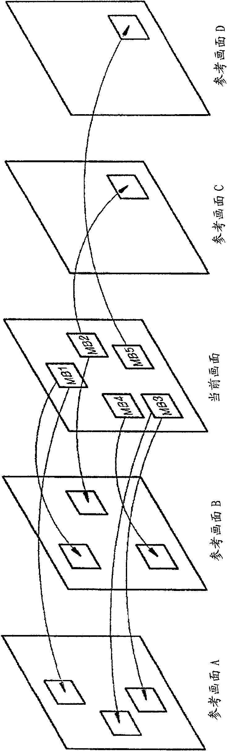
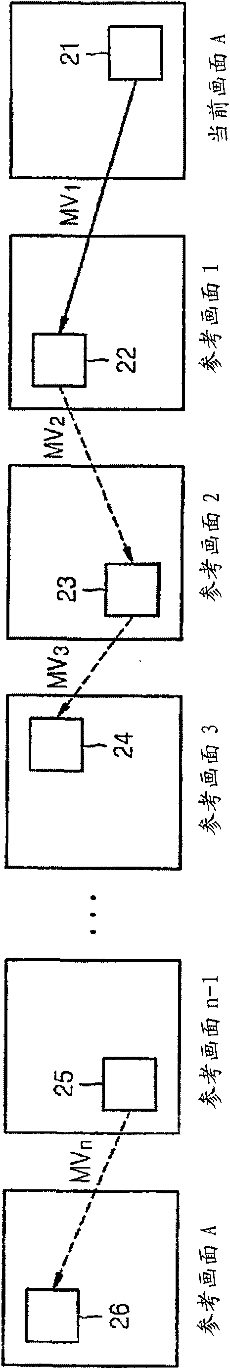
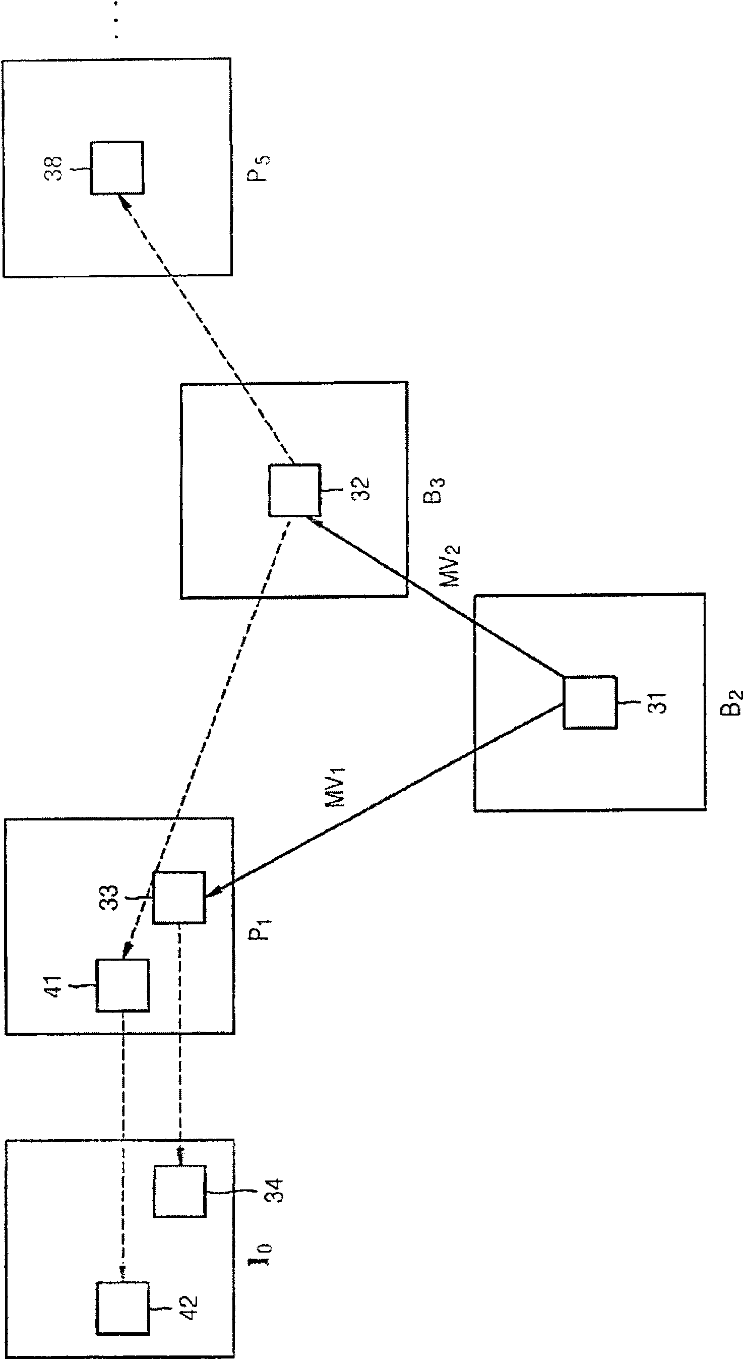
[0024] According to an aspect of the present invention, there is provided an image encoding method, comprising: determining the correspondence of a plurality of reference pictures to be used for predicting a current block of a current picture by tracking motion vector routes of corresponding regions of reference pictures referred to by the current block an area; generating a prediction block of the current block by calculating a weighted sum of corresponding areas of a plurality of reference pictures; and encoding a difference between the current block and the prediction block.

[0025] According to another aspect of the present invention, there is provided an image encoding device, including: a reference picture determining unit that determines a plurality of frames to be used for predicting the current block by tracking the motion vector route of the corresponding area of ​​the reference picture referenced by the current block. a corresponding area of ​​the reference picture;...


PUM


Abstract

The present invention discloses a method and apparatus for encoding/decoding an image using motion vector tracking. The image encoding method includes determining corresponding areas of a plurality of reference pictures that are to be used to predict a current block by tracking a motion vector route of a corresponding area of a reference picture referred to by the current block; generating a prediction block of the current block by calculating a weighted sum of the corresponding areas of the plurality of reference pictures; and encoding a difference between the current block and the prediction block.

Description

technical field [0001] Methods and apparatus consistent with the present invention relate to predictive encoding / decoding of pictures, and more particularly to encoding / decoding of pictures such that they continuously track the course of the motion vector of the current picture, determine a number of reference pictures, and use the reference Picture predictive coding of the current picture. Background technique [0002] When encoding video, the spatial and temporal redundancies of a sequence of images are removed to compress the sequence of images. To eliminate temporal redundancy, reference pictures located before or after the currently coded picture are used to search for regions of the reference picture that are similar to regions of the currently coded picture, to detect motion between the currently coded picture and corresponding regions of the reference picture, and encoding a residual between a predicted picture obtained by performing motion compensation based on the...

Claims


Application Information

Patent Timeline
IPC IPC(8): H04N7/32
Inventor 李教爀金素英
Owner SAMSUNG ELECTRONICS CO LTD
Why Eureka
Try Eureka