Printing medium detection system, printing medium detection method, and printing apparatus

A detection system and position detection technology, applied to printing devices, printing, typewriters, etc., can solve problems such as errors and low reflectivity

Inactive Publication Date: 2009-11-18
SEIKO EPSON CORP
View PDF1 Cites 4 Cited by
  • Summary
  • Abstract
  • Description
  • Claims
  • Application Information

AI Technical Summary

Problems solved by technology

[0006] But, even under the situation that the recording object is placed on the placing portion, the upper surface of the recording object corresponding to the hole position is low reflectivity such as black, or the ink of the color of the low reflectivity is used for this portion. Even when recording is performed, it may be wrongly judged that the document is not recorded

Method used


Image

  • Printing medium detection system, printing medium detection method, and printing apparatus
  • Printing medium detection system, printing medium detection method, and printing apparatus
  • Printing medium detection system, printing medium detection method, and printing apparatus

Examples


Embodiment 1

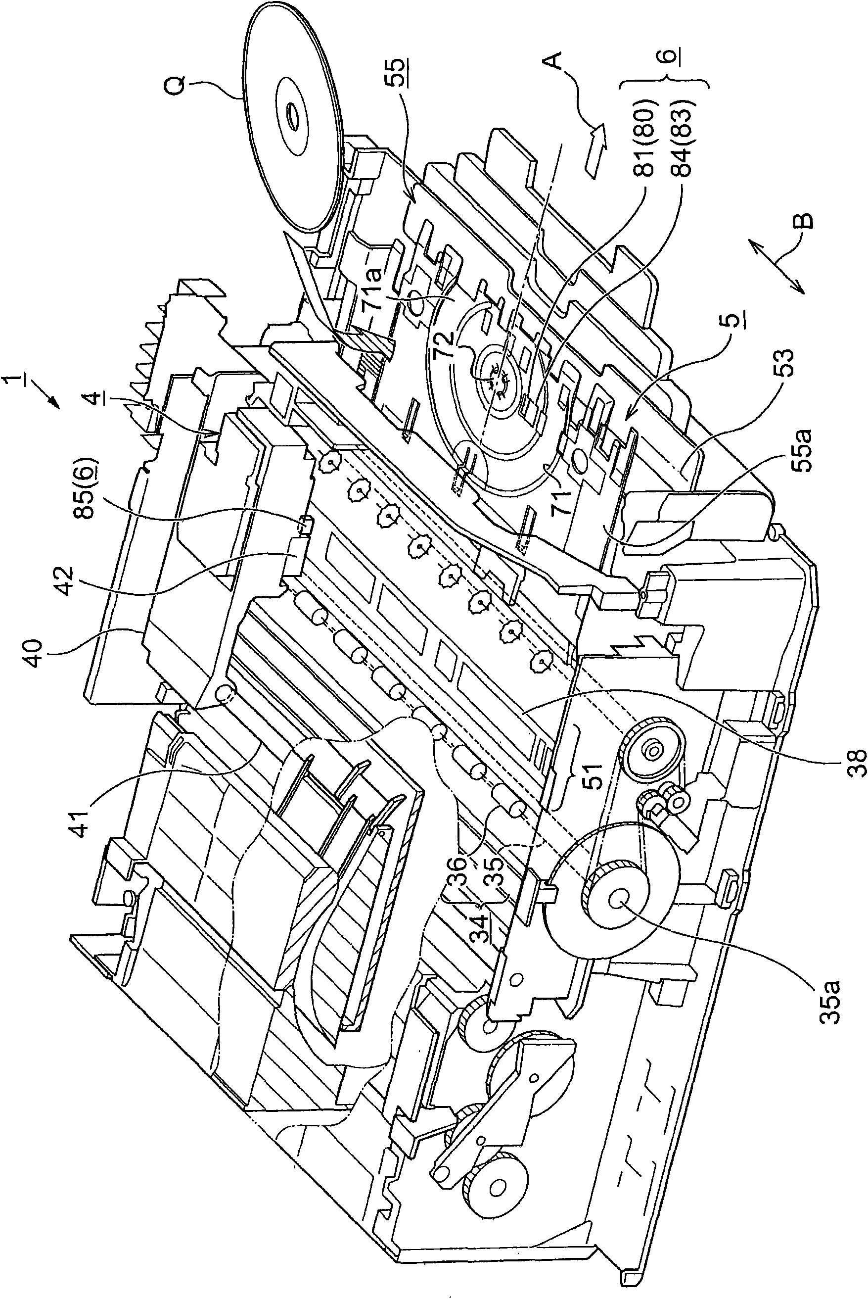
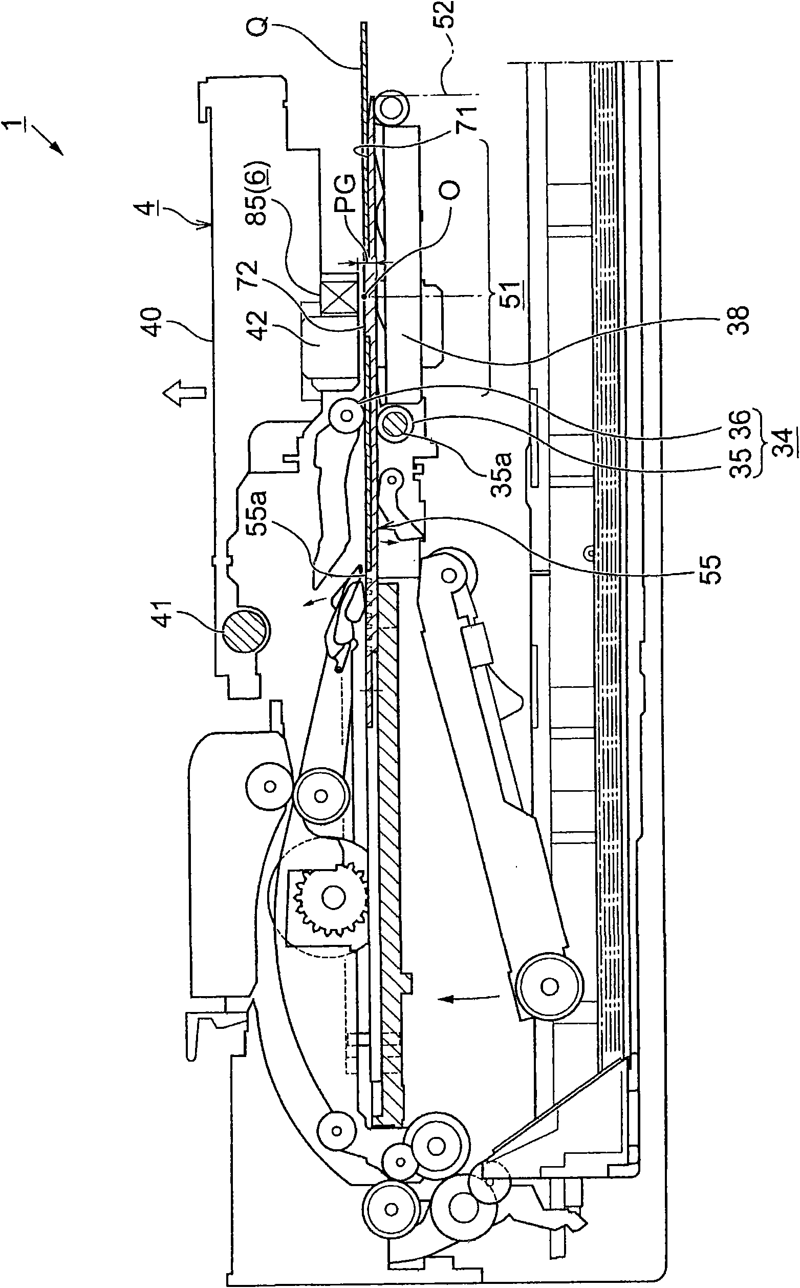
[0058] Next, according to the drawings, the structure of the presence / absence detection system 6 of the recorded material of this embodiment applied to the inkjet printer 1 configured as described above, and the present invention implemented by using the presence / absence detection system 6 of the recorded material The method for detecting the presence or absence of the recorded object will be specifically explained.

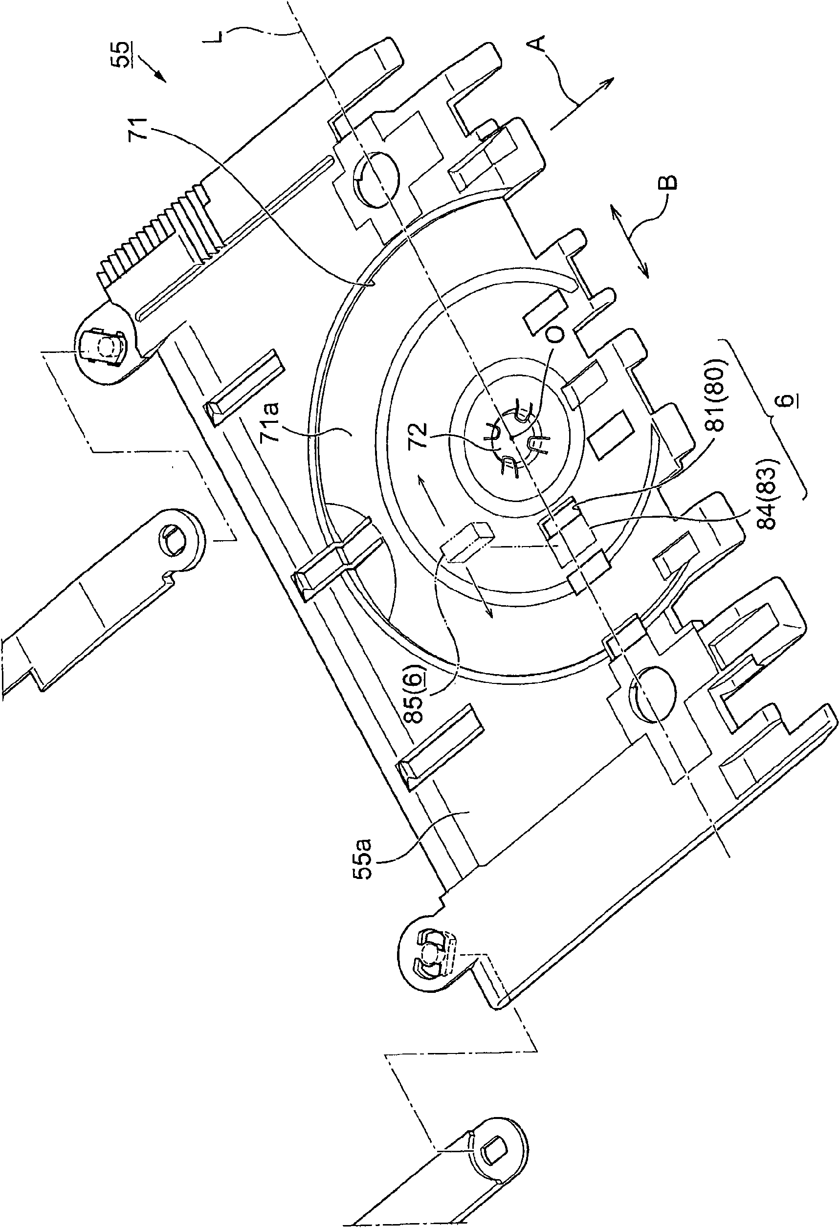
[0059] image 3 Is a perspective view showing the holding tray, Figure 4 It is a top view of the holding tray with a 12cm diameter recording object placed at the detection execution position. In addition, Figure 5 It is a top view of the holding tray on which the object to be recorded with a diameter of 8 cm is placed at the detection execution position.

[0060] The basic configuration of the recording object presence detection system 6 of this embodiment is provided with a dark mark 80 provided in a placement recess 71 on the holding tray 55 for placing the reco...

Embodiment 2

[0076] The presence or absence detection system 6 of the recorded object of the present invention, the presence or absence detection method of the recorded object executed by using the presence or absence detection system 6 of the recorded object, and the recording of the presence or absence detection system 6 provided with the recorded object The device 1 has a basic structure as described above, but needless to say, it is also possible to modify or omit a partial structure within a range that does not deviate from the gist of the present invention.

[0077] Figure 7 It is a plan view showing another example in which the arrangement of dark marks and light marks is different. That is, instead of the structure in which the bright color mark 83 is provided in the vicinity of the scanning direction B of the reflective sensor 85 with respect to the dark color mark 80, such as Figure 7 As shown, the bright color mark 83 may be provided at a position near the conveying direction A o...

Embodiment 3

[0079] Figure 8 It is a plan view showing another embodiment in which a plurality of sets of dark marks and bright marks are arranged. In addition to only one set of the dark mark 80 and the light mark 83, multiple sets may be set. In addition, when a plurality of sets of the dark mark 80 and the light mark 83 are provided, the arrangement pattern of the dark mark 80 and the light mark 83 can be different for each group. By the way, Figure 8 On a straight line L parallel to the width direction B passing through the center O of the holding protrusion 72 of the holding tray 55, a set of dark marks 80L, 80R and light marks 83L, 83R are provided on the left and right sides of the holding protrusion 72. .

[0080] Furthermore, the width dimension and arrangement position of the dark mark 80R and the light mark 83R facing the right are different from the width dimension and arrangement position of the dark mark 80L and the light mark 83L facing the left, thereby reducing the factor. Th...


PUM


Abstract

The present invention provides a printing medium detection system and a printing medium detection method, capable of detecting whether a set portion locating on a retaining tray is provided with a printing medium or not accurately. The printing medium detection system includes: a dark mark (80) provided in a set portion (71) for setting a printing medium (Q) on a retaining tray (55); a bright mark (83) provided in the set portion (71) for setting the printing medium (Q) on the retaining tray (55); and a reflective sensor (85) that detects the existence of a printing medium by using light individually irradiated to the position of the dark mark (80) and the position of the bright mark (83) and reflected from the positions.

Description

Technical field [0001] The present invention relates to a system for detecting the presence or absence of a recorded object for detecting whether or not the object to be recorded is placed on a holding disc, a method for detecting the presence or absence of a recorded object, and a printer provided with the presence or absence detection system for the recorded object A conceptual recording device including a multifunction machine represented by a fax machine or a copier. Background technique [0002] Hereinafter, an inkjet printer as an example of a recording device is selected as an example for description. In inkjet printers, there are two types of soft recorded materials that can not be independent of printing paper and film, and independent hard recorded materials represented by optical disks (CD-R and DVD-R, etc.). A printer (for example, Patent Document 1, etc.) configured to selectively perform recording. In addition, when recording on the CD-R and other optical discs, eit...

Claims


Application Information

Patent Timeline
Patent Type & Authority Applications(China)
IPC IPC(8): B41J11/00B41J3/407
CPCB41J3/4071
Inventor 小室新太郎筱崎畅彦泷川智也
Owner SEIKO EPSON CORP
Why Eureka
Try Eureka