Basin wrench

A sink and wrench technology, applied in the direction of wrenches, manufacturing tools, wrenches, etc., can solve the problems of limiting the use of known wrenches

Inactive Publication Date: 2009-11-18
EMERSON ELECTRIC CO
View PDF0 Cites 5 Cited by
  • Summary
  • Abstract
  • Description
  • Claims
  • Application Information

AI Technical Summary

Problems solved by technology

This limits the use occasions of this known wrench

Method used


Image

  • Basin wrench
  • Basin wrench
  • Basin wrench

Examples


Embodiment Construction

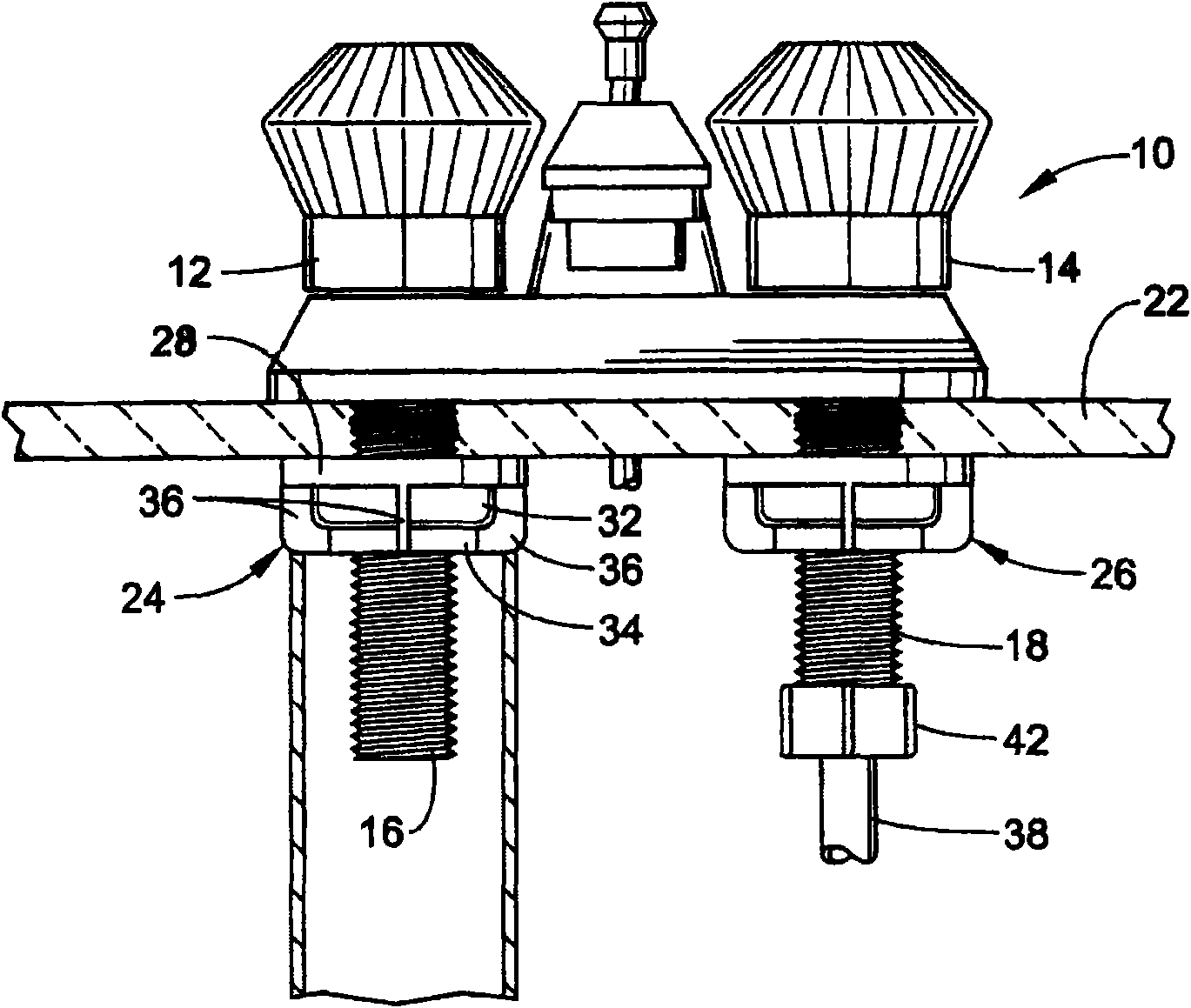
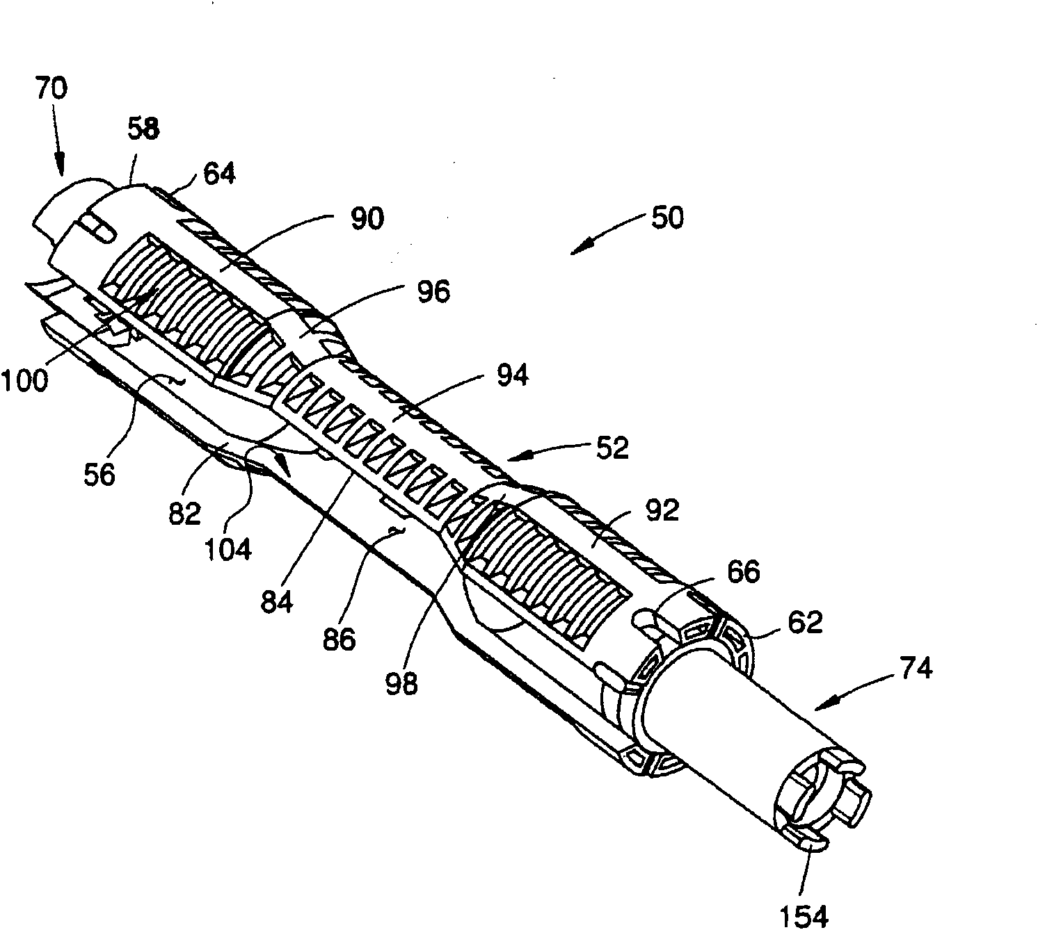
[0025] refer to image 3 , a sink wrench 50 is used to turn sink nuts, such as sink nuts 24 and 26 shown in FIG. 1, to attach the faucet unit to the countertop. The sink wrench 50 is also useful in many other applications such as tightening 7 / 8" supply pipe nuts, plastic wing supply nuts, 1" supply pipe nuts (and nuts with other eg metric sizes) and supply pipe shutoff valves. Accordingly, the present invention should not be limited to a wrench for loosening sink nuts only, but should be broadly interpreted. In the illustrated embodiment, the sink nut 50 is made from a molded rigid plastic material; however, other materials such as metal, composite materials, etc. can also be used.

[0026] according to image 3 In the illustrated embodiment, the sink wrench 50 generally includes an elongated wrench body 52 having a generally hourglass-shaped configuration that is substantially axially symmetrical about a longitudinal axis 54 ( Figure 4 ), the longitudinal axis 54 is also th...


PUM


Abstract

A basin wrench (50) includes a body (52) having a hand gripping portion (94) being configured such that a hand of a user of the basin wrench can grip the body and provide sufficient torque to rotate the body to tighten an associated basin nut. The body can include a longitudinal slot (86) generally parallel with a longitudinal axis of the body. The basin wrench can also include an insert (70) configured to engage an associated nut and / or an associated water shut-off valve. An additional insert (74) can be provided to engage a strainer basket and / or be engaged by an associated wrench or rod. A method for rotating a basin nut is also provided.

Description

[0001] Cross References to Related Applications [0002] This application claims priority to US nonprovisional application Serial No. 11 / 499408, filed August 4, 2006. Application Serial No. 11 / 499408 is hereby incorporated by reference in its entirety. Background technique [0003] Basin nuts, which are used to secure kitchen and vanity faucets, kitchen spray hoses, toilet float valves, etc., are often located in tight areas that are difficult to engage with a wrench. In recent years, plastic nuts have been used to secure faucets, float valves, etc. Many plastic nuts have wings or flanges to facilitate turning the nut by hand. However, in many cases a wrench is still required to handle such nuts, which may have become "frozen" there due to overtightening or due to minerals in the water, to ensure tightening and loosening of the nuts. [0004] Referring to FIG. 1 , a typical vanity faucet unit 10 includes hot and cold faucets 12 and 14 each having a respective screw 16 and 1...

Claims


Application Information

Patent Timeline
IPC IPC(8): B25B13/48
CPCB25B13/48B25B13/481
Inventor 布赖恩·M·阿德金斯斯蒂芬·M·麦克希格伦·R·查蒂尔
Owner EMERSON ELECTRIC CO
Why Eureka
Try Eureka