Motor vehicle pneumatic jacklift system

a pneumatic jacklift and motor vehicle technology, applied in the field of pneumatic jacklift systems, can solve the problems of difficult operation and much more dangerous, and achieve the effects of low manufacturing cost, easy retrofitting, and easy and efficient manufacturing and marketing

Inactive Publication Date: 2005-05-24
WILLETT MICHAEL J
View PDF56 Cites 65 Cited by
  • Summary
  • Abstract
  • Description
  • Claims
  • Application Information

AI Technical Summary

Benefits of technology

[0025]It is therefore an object of the present invention to provide a new motor vehicle pneumatic jacklift system that provides in the apparatuses and methods of the prior art some of the advantages thereof, while simultaneously overcoming some of the disadvantages normally associated therewith.
[0026]It is another object of the present invention to provide a new and improved after-market pneumatic jacklift system that may be easily retrofitted to existing motor vehicles.
[0027]It is another object of the present invention to provide a new and improved new motor vehicle pneumatic jacklift system that

Problems solved by technology

This system replaces the need for portable manual jack, wh

Method used


Image

  • Motor vehicle pneumatic jacklift system
  • Motor vehicle pneumatic jacklift system
  • Motor vehicle pneumatic jacklift system

Examples


Embodiment Construction

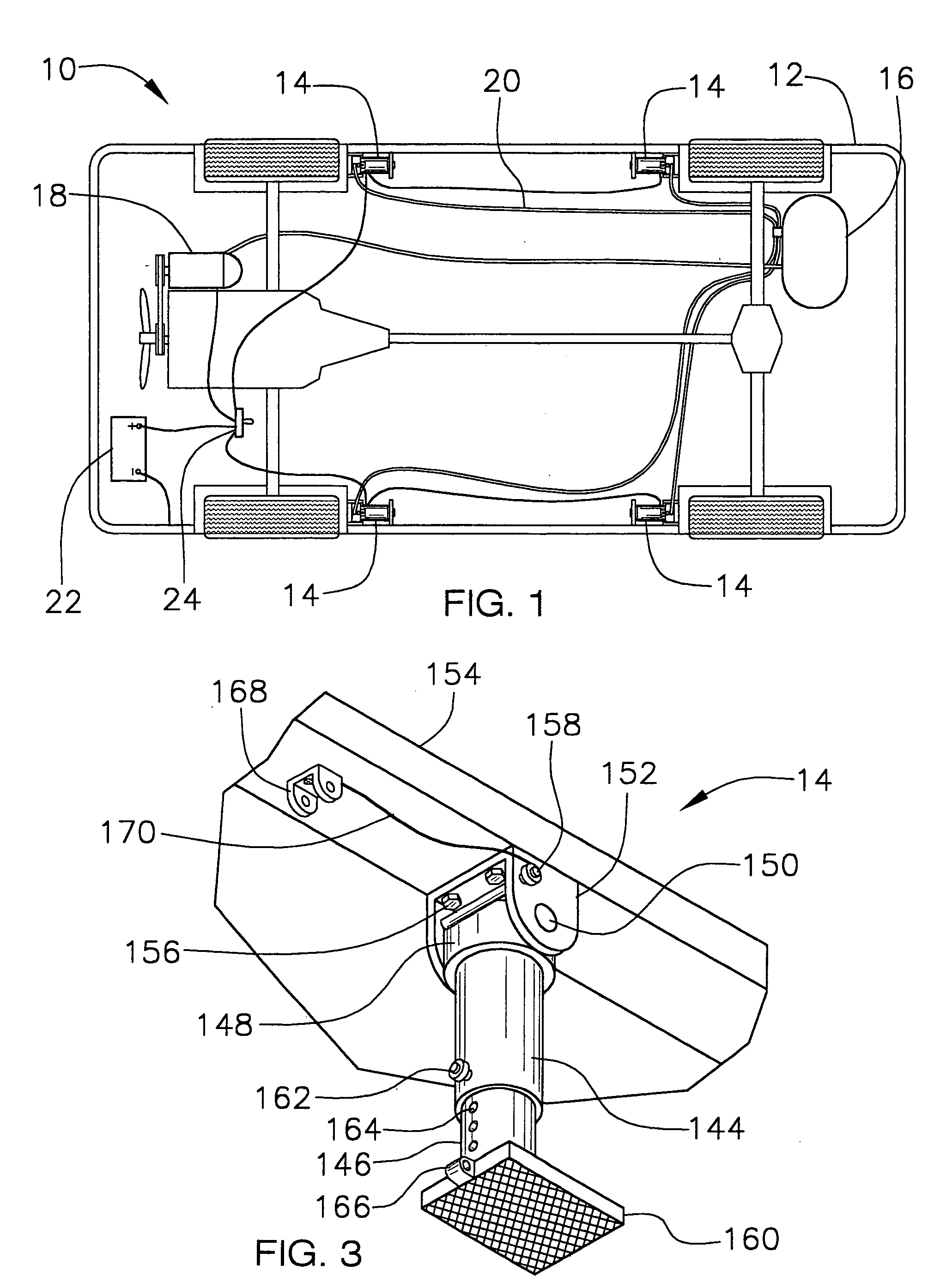
[0039]Referring now to the drawings, and particularly to FIGS. 1–6, a preferred embodiment of the motor vehicle pneumatic airlift system of the present invention is shown and generally designated by the reference numeral 10.

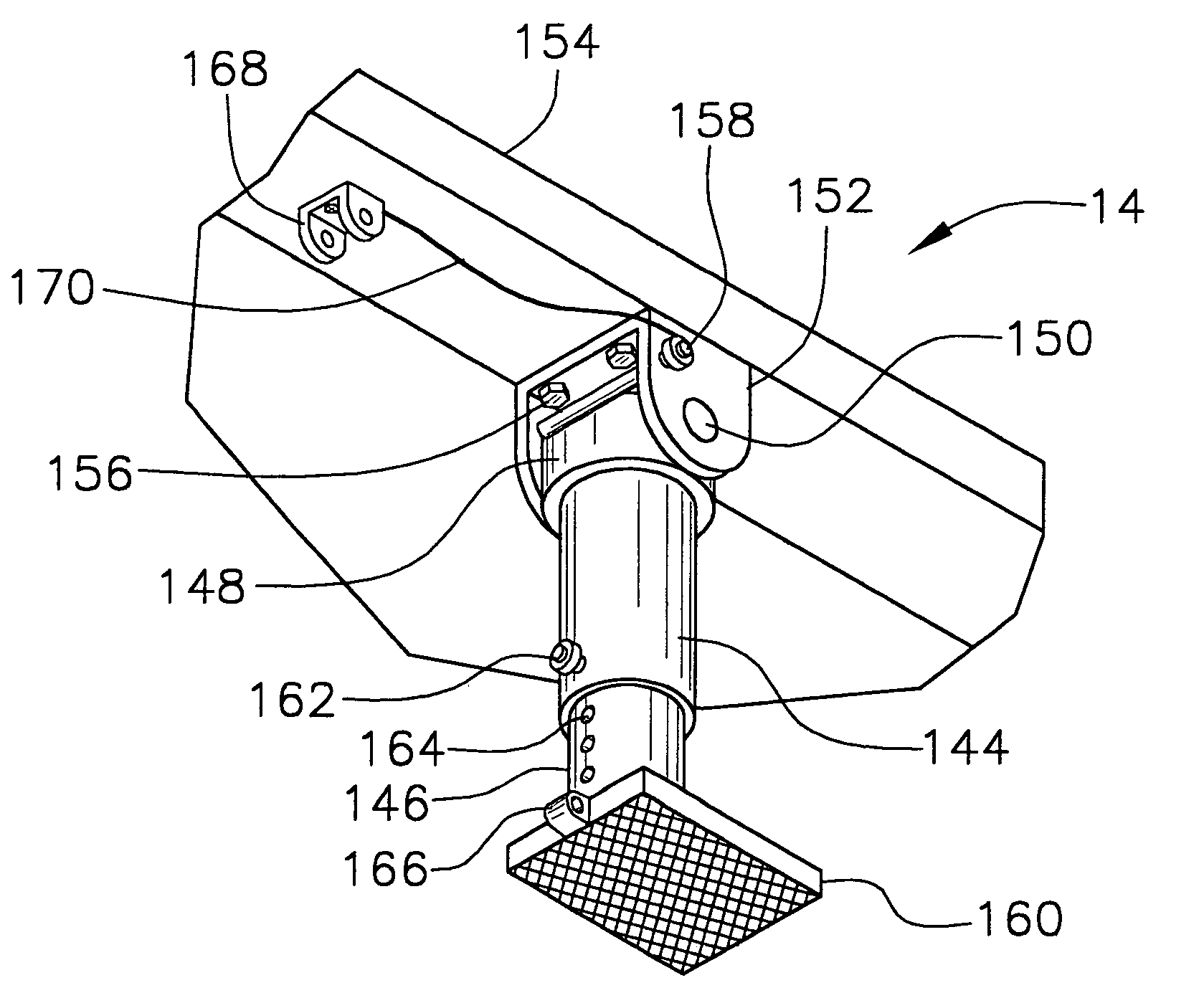
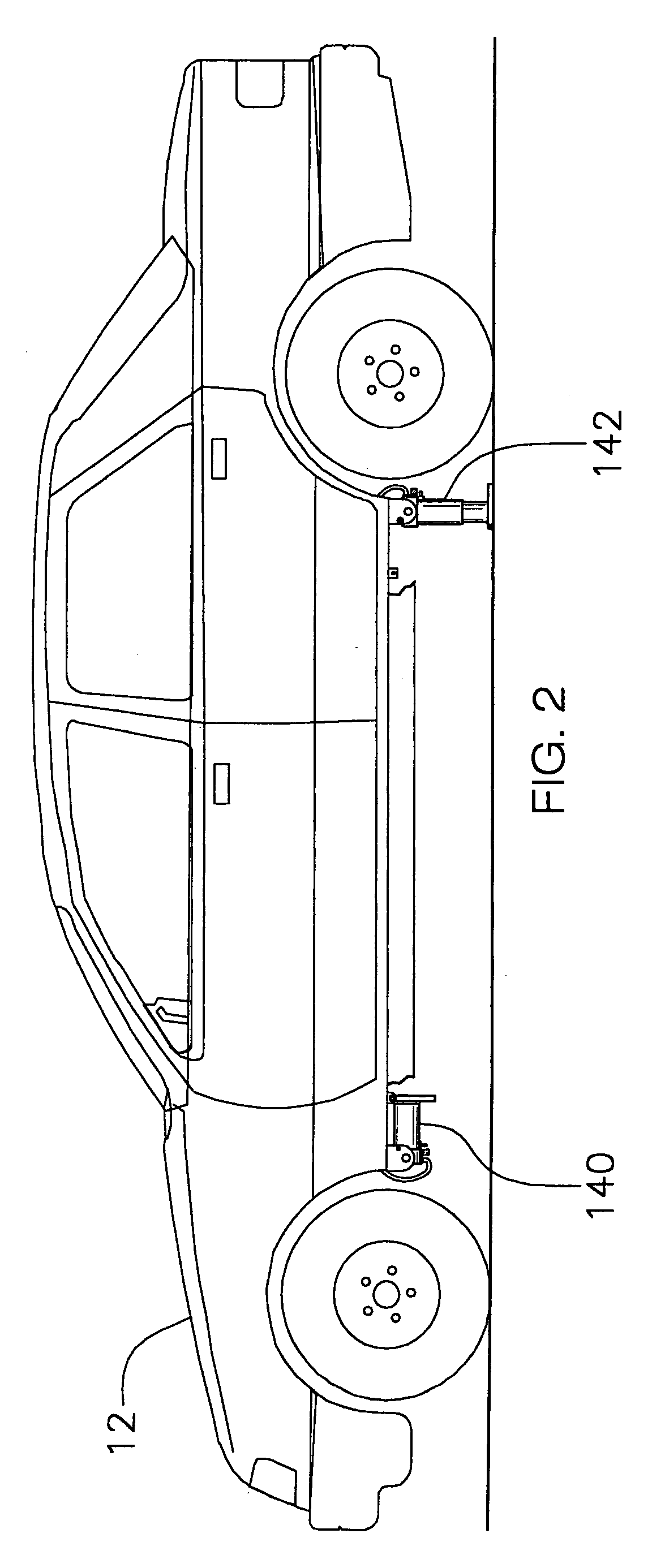
[0040]In FIG. 1, a new and improved pneumatic airlift system 10 of the present invention for use in changing a flat tire on a motor vehicle is illustrated and will be described. More particularly, the pneumatic airlift system 10 is installed to the under frame of a motor vehicle 12. The system uses up to four jacklifts (jacks) 14, typically with two installed just behind the front tires and two just in front of the rear tires. A high-pressure air storage tank 16 is connected by an air hose or tubing to the output of an air compressor 18, which is mechanically belt-driven from the motor vehicle's engine. Additional air hoses 20 are used to deliver compressed air to the individual jacklifts. Also, a system activation switch 24, located inside the motor vehicle to p...


PUM

PropertyMeasurementUnit
Pressureaaaaaaaaaa
Flow rateaaaaaaaaaa
Heightaaaaaaaaaa

Abstract

A permanently mounted pneumatic jack (jacklift) system for motor vehicles, as well as an impact wrench for removing and installing lug nuts. The system provides a quick and safe means of lifting one or more tires off the ground for replacement of a spare or rotating the tires on a motor vehicle. The present invention comprises two or more (typically four) pneumatic jacks, a system ON/OFF switch, an air compressor, a 120-psi air tank, air lines (hoses), individual jack extend/retract switches, jack position-locking pins, safety-locking pins, and impact wrench. Each jack can be locked in a horizontal stowaway or vertical operational position. The jack is cylindrical shaped with a telescopic body that can be extended or retracted as needed to raise and lower the vehicle. A solid cylindrical lift rod slides inside a cylindrical outer housing with a high-pressure seal means used to maintain pressure on the support rod. A ground support foot (plate) is mounted on the lower end of the solid cylindrical lift rod to provide sufficient traction with the ground to support the lifting process. A quick release air coupler is included on the pneumatic chamber to support the use of an air hose and impact wrench. An extend/retract toggle switch is included on each jack to control a solenoid valve to allow the air to flow into the jack. A quick release safety-locking pin is used to mechanically pin the solid cylindrical lift rod to the outer housing once the desired height is achieved to assure that the vehicle does not fall down in the event of a high-pressure air loss, thereby providing safety to the person(s) working around the vehicle. An air compressor located in the engine compartment of the vehicle is mechanically belt-driven off the engine. A high-pressure air line carries the air to a high-pressure (at least 120-psi) air tank located in the trunk or other suitable storage area on the vehicle. Separate air lines extend from the air tank to the individual jacks.

Description

BACKGROUND OF THE INVENTION[0001]1. Field of the Invention[0002]The present invention relates to a pneumatic jacklift system for use in connection with motor vehicles. The pneumatic jacklift system has particular utility in connection with changing a flat tire or rotating the tires on an automobile or truck.[0003]2. Description of the Prior Art[0004]Anyone who has ever changed a tire on an automobile or truck, especially on a busy street or highway, knows the danger and problems involved with getting portable jack to raise the vehicle off the ground and changing the tire. There is a need for a quicker and safer means of lifting a flat tire off the ground for replacement with a spare tire.[0005]The use of pneumatic jack systems attached to motor vehicles is known in the prior art. For example, U.S. Pat. No. 4,993,688 to Mueller et al. discloses two built-in pneumatic power jacks, one mounted centrally to the front of the vehicle and the other mounted centrally to the rear of the vehi...

Claims


Application Information

Patent Timeline
IPC IPC(8): B60S9/12B60S9/00B66F3/00B66F3/46B66F3/24
CPCB60S9/12B66F3/247B66F3/46Y10T29/5383Y10T29/49822Y10T29/4973Y10T29/49721
Inventor WILLETT, MICHAEL J.
Owner WILLETT MICHAEL J
Why Eureka
Try Eureka