
Fire hydrant security cap closure system

a technology for fire hydrants and security caps, which is applied in the direction of valve operating means/release devices, drawing-off water installations, manufacturing tools, etc., can solve the problems the cap can spin freely, etc., and achieve the effect of difficult to remove with conventional tools

Inactive Publication Date: 2009-12-10
RUHS JACK
View PDF4 Cites 61 Cited by
  • Summary
  • Abstract
  • Description
  • Claims
  • Application Information

AI Technical Summary

Benefits of technology

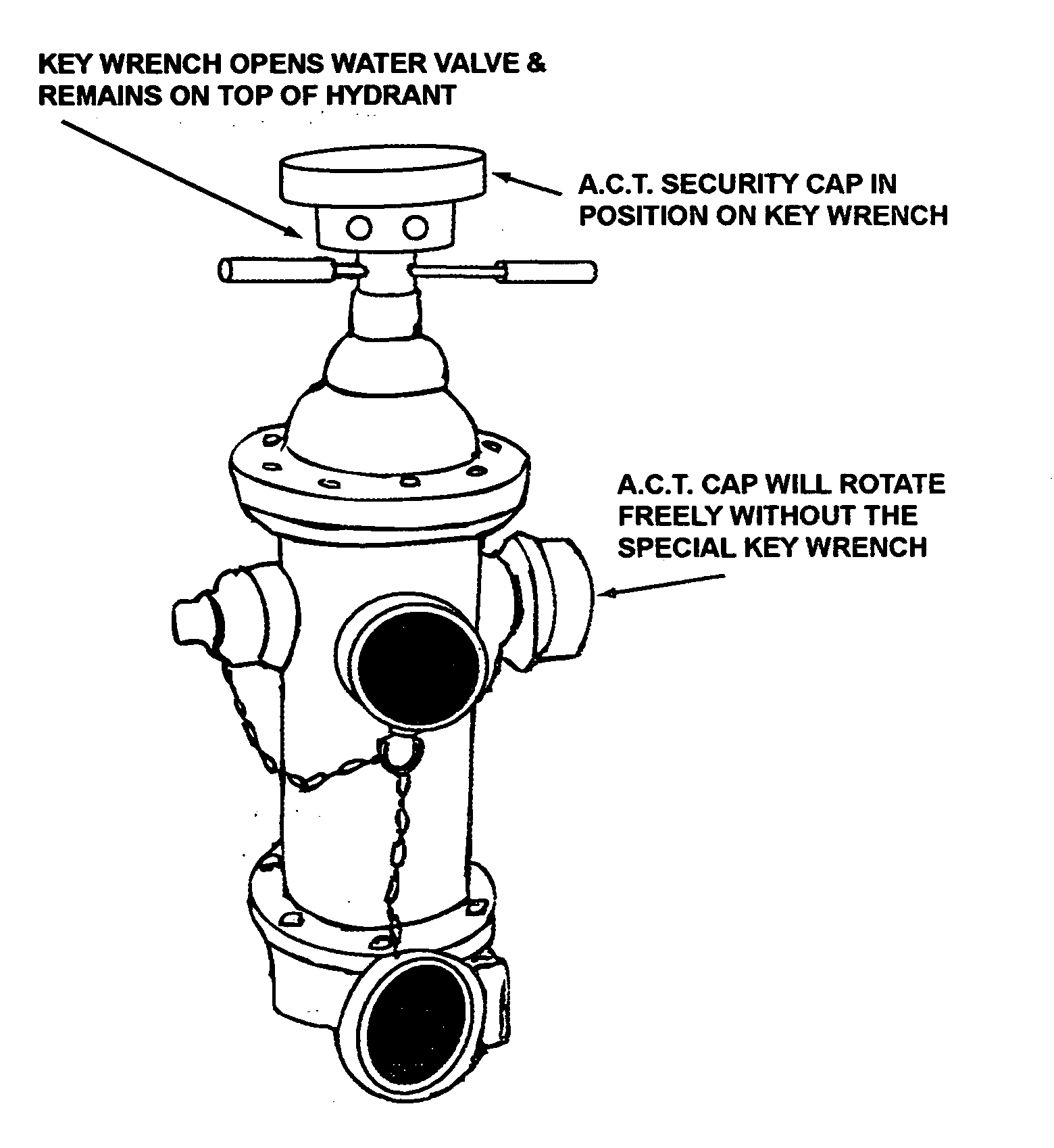
[0004]The objective of this invention is to provide a means to prevent theft of water, cap theft, and terrorist access to the water supply. The cap can spin freely and is difficult to remove with conventional tools. A unique key wrench, designed to mate with the cap, is used to provide security to hydrants. A tracking device such as a GPS unit can be inserted into the key wrench for locating the key wrench should it be lost or stolen. When the key wrench is not in use, a cradle can be used to charge the battery of the GPS unit.
[0005]The objective of this invention can be achieved by providing a fire hydrant security system with an inner cap having means for attaching an outlet port of a fire hydrant in a fixed position which includes a member capable of extending from the periphery of the inner cap into a slot in the inner part of an outer cap and having means for retracting and retaining the position of the member in the inner cap, wherein said outer cap includes means for attaching the outer cap to the inner cap so that the outer cap can spin freely with respect to the inner cap, and a key wrench having means for fitting the key wrench over the outer cap and for aligning the outer cap and key wrench in a fixed position wherein the key wrench has a magnet located on the wall of the key wrench that becomes aligned with a slot on inner wall of the outer cap and wherein the rotation of the key wrench causes the magnet to align with the member and to extend the member into the slot on the inside of the outer cap thereby joining the outer cap to the inner cap.

Problems solved by technology

The cap can spin freely and is difficult to remove with conventional tools.

Method used


Image

  • Fire hydrant security cap closure system
  • Fire hydrant security cap closure system
  • Fire hydrant security cap closure system

Examples


Embodiment Construction

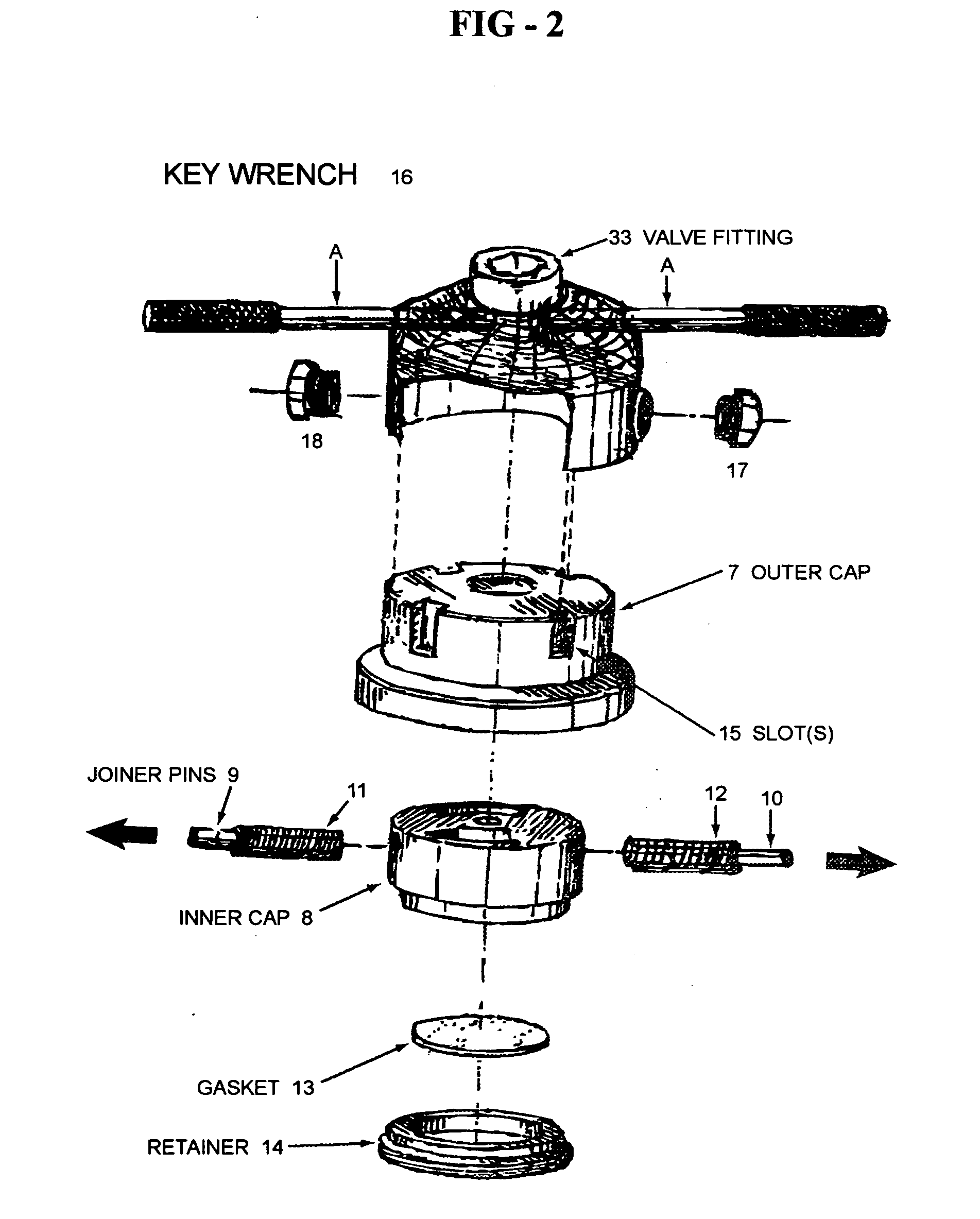
[0012]FIGS. 2, 3A and 3B show an outer cap 7 that spins on inner cap 8. Inner cap 8 and outer cap 7 are joined with means for retaining and allowing outer cap 7 to spin freely around inner cap 8. Inner cap 8 has joiner pins 9 and 10 that are restrained from extending in from the periphery of the inner cap peripherally extending in a radial direction from the center of the cap by springs 11 and 12. FIG. 3A shows inner cap 8 having threads 32 for closing outlet port 2

[0013]The outer cap 7 has slots 15 those mates with the protrusions 28 on the inner wall of key wrench 16 when key wrench 16 fits over outer cap 7. When the protrusions 28 are mated with the slots the key wrench can turn the outer cap. Preferably there are 4 slots cut into the periphery of the inner cap at 90 degrees spacing for joining the key wrench with the outer cap. The term slot includes any narrow opening or groove or hole.

[0014]Retainer ring 14 has threads that mate with the threads 37 on the outer cap 7. Once the...


PUM


Abstract

This invention provides a fire hydrant security system with an inner cap having means for attaching an outlet port of a fire hydrant in a fixed position which includes a member capable of extending from the periphery of the inner cap into a slot in the inner part of an outer cap and having means for retracting and retaining the position of the member in the inner cap, wherein said outer cap includes means for attaching the outer cap to the inner cap so that the outer cap can spin freely with respect to the inner cap, and a key wrench having means for fitting the key wrench over the outer cap and for aligning the outer cap and key wrench in a fixed position wherein the key wrench has a magnet located on the wall of the key wrench that becomes aligned with a slot on inner wall of the outer cap and wherein the rotation of the key wrench causes the magnet to align with the member and to extend the member into the slot on the inside of the outer cap thereby joining the outer cap to the inner cap.

Description

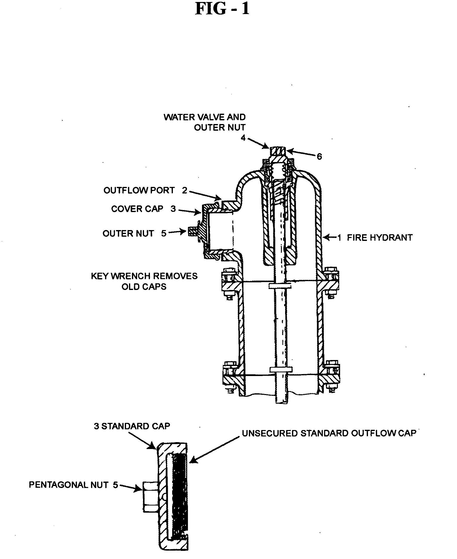
FIELD OF THE INVENTION[0001]This invention relates to the problem of making our public water supply safer by protecting the access to the water supply through the fire hydrants in public places.BACKGROUND OF THE INVENTION[0002]FIG. 1 shows a conventional fire hydrant 1 having an outflow port 2 which is protected by a cap 3 and a water valve 4. The same type of tool can be used to turn nuts 5 and 6. Turning the nut 5 removes the outflow port cover and turning nut 6 opens the water valve to allow the water to flow through the outflow port 2. Because these caps can be removed with readily available tools, such as a pipe key or spanner wrench the conventional lids or covers are not sufficiently protected from unauthorized access.[0003]The prior art has made many attempt to provide a secure cap for fire hydrant. U.S. Pat. No. 5,072,750 filed on Dec. 17, 1991, which is incorporated by reference in the entirety, shows a rotating cap that uses a magnet wrench to attach the cap to a plate th...

Claims


Application Information

Patent Timeline
IPC IPC(8): E03B9/06F16K35/16
CPCF16K35/16E03B9/06Y10T70/5628Y10T137/5468Y10T137/7131
Inventor RUHS, JACK
Owner RUHS JACK
Learn More