Mechanism for the deployment of endovascular implants

An implant and user technology, applied in the field of coupling components, can solve problems such as limitations, and achieve the effect of control improvement and cost increase

Inactive Publication Date: 2009-12-02
MICROVENTION INC
View PDF23 Cites 14 Cited by
  • Summary
  • Abstract
  • Description
  • Claims
  • Application Information

AI Technical Summary

Problems solved by technology

However, as a conventional microcoil technique, the successful application of the GDC approach has been largely limited to small aneurysms with narrow necks.

Method used


Image

  • Mechanism for the deployment of endovascular implants
  • Mechanism for the deployment of endovascular implants
  • Mechanism for the deployment of endovascular implants

Examples


Embodiment Construction

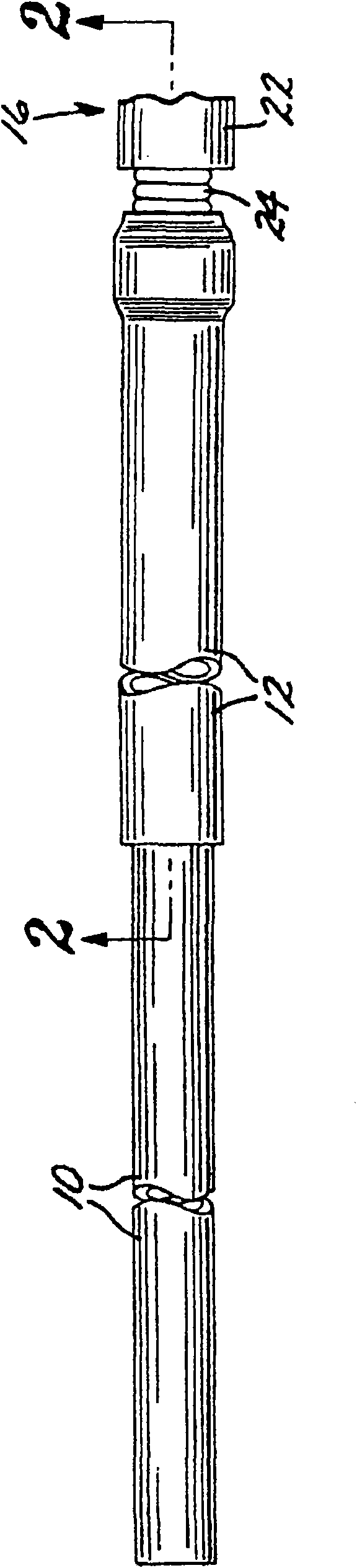
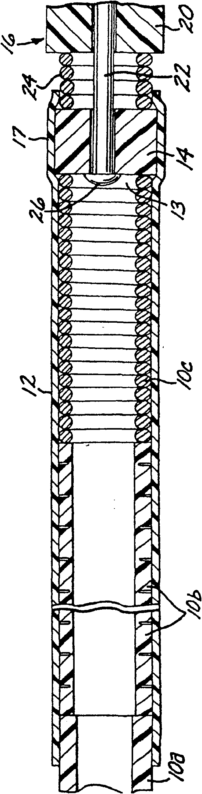
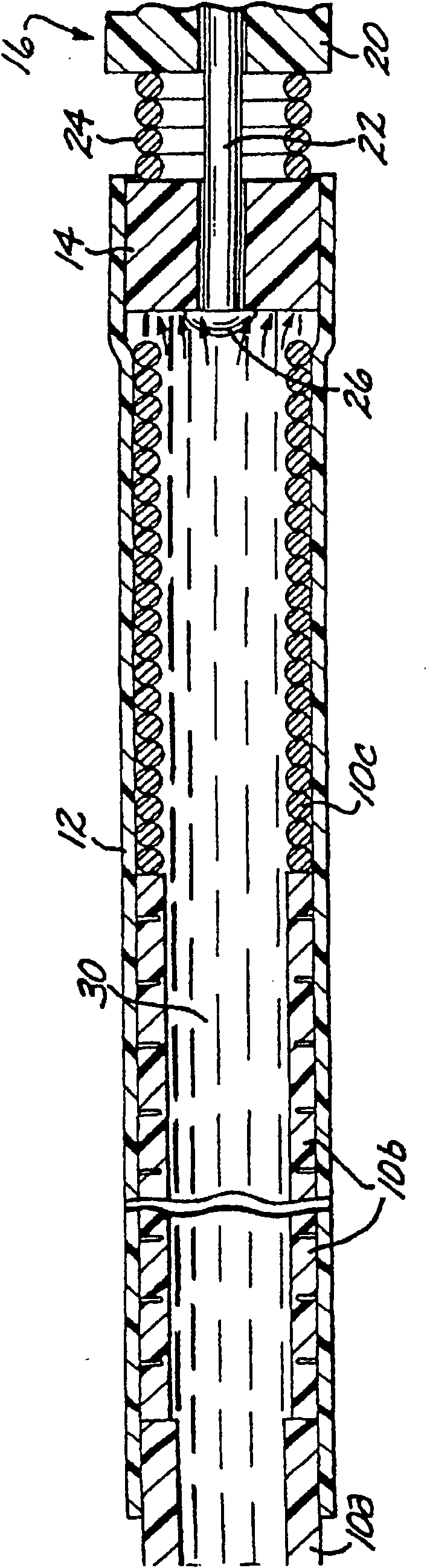
[0052] first reference figure 1 , according to the present invention, a deployment mechanism for an intravascular device comprises a proximal end 11 having an open (see Figure 11 ) and an extended flexible hollow arrangement tube 10 terminating in the distal portion of the open distal end 13, forming a continuous fluid passage lumen 15 between the proximal and distal ends. A retaining sleeve 12 is secured around the distal portion of the deployment tube 10 and includes a distal extension 17 extending a short distance beyond the distal end 13 of the deployment tube. The deployment mechanism also includes a coupling element 14 secured to the proximal end (only the proximal end of which is shown) of a filamentary intravascular device 16, which may be, for example, an embolic implant.

[0053] The deployment tube 10 is made of stainless steel and is preferably formed in three sections, each sized to pass through a typical microcatheter. The proximal or trunk portion 10a is the ...


PUM

PropertyMeasurementUnit
lengthaaaaaaaaaa
lengthaaaaaaaaaa

Abstract

A mechanism for the deployment of a filamentous endovascular device includes a flexible deployment tube having an open proximal end, and a coupling element attached to the proximal end of the endovascular device. The deployment tube includes a distal section terminating in an open distal end, with a lumen defined between the proximal and distal ends. A retention sleeve is fixed around the distal section and includes a distal extension extending a short distance past the distal end of the deployment tube. The endovascular device is attached to the distal end of the deployment tube by fixing the retention sleeve around the coupling element, so that the coupling element is releasably held within the distal extension of the deployment tube. In use, the deployment tube, with the implant attached to its distal end, is passed intravascularly through a microcatheter to a target vascular site until the endovascular device is located within the site. To detach the endovascular device from the deployment tube, a liquid is injected through the lumen of the deployment tube so as to apply pressure to the upstream side of the coupling element, which is thus pushed out of the retention sleeve by the fluid pressure. The coupling element may include an internal or peripheral purge passage that allows air to be purged from the microcatheter prior to the intravascular passage of the endovascular device.

Description

[0001] Cross References to Related Applications [0002] This application is a continuation-in-part of co-pending application Serial No. 10 / 143,724, published as U.S. Patent No. 6,689,141, filed May 10, 2002; in turn, this application is an application filed on October 18, 2000 Continuation-in-Part of Serial No. 09 / 692,248, now US Patent No. 6,607,538. The contents of these two prior applications are incorporated herein by reference. [0003] Federally funded research or development [0004] none Background technique [0005] The present invention relates to the field of methods and devices for embolization of vascular aneurysms and similar vascular abnormalities. More particularly, the present invention relates to a mechanism for deploying an intravascular implant, such as a microcoil, within a target vessel site and releasing or disengaging the implant at the site. [0006] Embolization of blood vessels is desired in many clinical situations. For example, vascular embol...

Claims


Application Information

Patent Timeline
Patent Type & Authority Applications(China)
IPC IPC(8): A61F2/84A61B17/12A61L31/04A61L31/08A61B17/00
CPCA61B17/12163A61B2017/00539A61B17/12022A61B2017/00867A61B17/1214A61B2017/1205A61B2017/12063A61B17/1219A61B2017/00477
Inventor 迪安·谢弗布赖恩·考克斯马修·菲茨雷乐雅娟
Owner MICROVENTION INC
Why Eureka
Try Eureka