Supercharge Your Innovation With Domain-Expert AI Agents!

Electropneumatic valve

A pneumatic valve and electric technology, applied in the direction of non-electric variable control, fluid pressure actuator, servo motor assembly, etc., can solve the problem that the pneumatic amplifier does not directly follow

Inactive Publication Date: 2009-12-16
ABB TECH AG
View PDF1 Cites 1 Cited by
  • Summary
  • Abstract
  • Description
  • Claims
  • Application Information

AI Technical Summary

Problems solved by technology

Due to the offset between the forward stroke characteristic curve and the return stroke characteristic curve, the pneumatic amplifier does not directly follow the electrical adjustment value

Method used


Image

  • Electropneumatic valve
  • Electropneumatic valve
  • Electropneumatic valve

Examples


Embodiment Construction

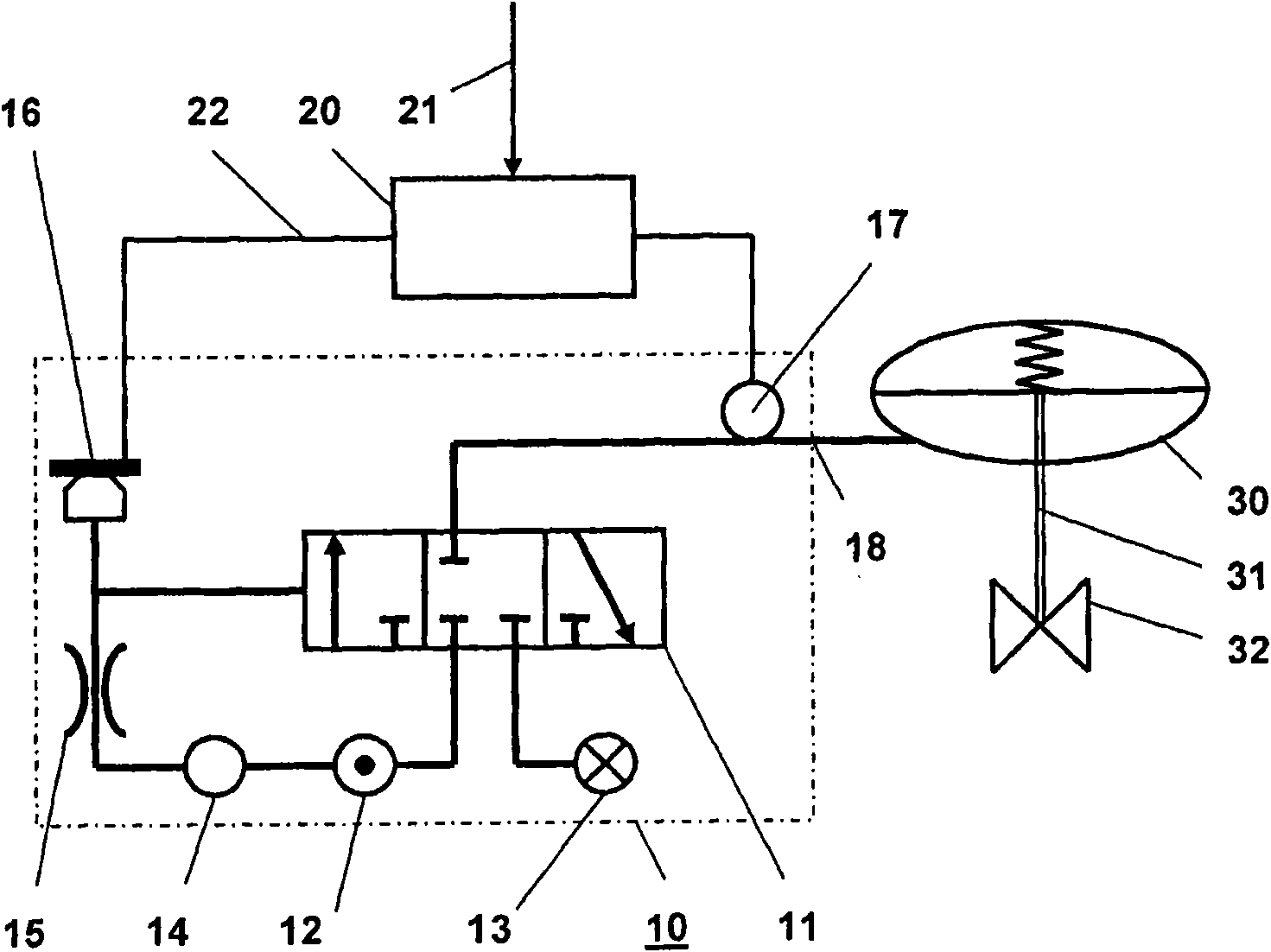
[0031] figure 1 Shown is an electropneumatic valve 10 for controlling a single-acting pneumatically adjustable drive 30 with an electropneumatic transducer 16 and a pneumatic amplifier with a valve device 11 for selectively switching the The connecting channel 18 of the actuating drive 30 is connected to the supply air channel 12 or to the exhaust air channel 13 . The valve device 11 is preferably designed as a 3 / 3-way valve 11 with a sealing medium position.

[0032]The 3 / 3-way valve 11 with a sealing medium position is designed to selectively connect the connecting channel 18 to the actuating drive 30 with the supply air channel 12 or with the exhaust air channel 13 . The prescribed actuation of the 3 / 3-way valve 11 with the sealing medium position takes place by the electropneumatic transducer 16 as a function of the electrical control signal 22 . For this purpose, an electropneumatic transducer 16 is connected via a pressure regulator 14 and a throttle 15 to the supply a...


PUM


Abstract

An electropneumatic valve is disclosed for controlling a pneumatic actuator drive. The valve can have at least one electropneumatic transducer and a pneumatic booster, which has at least one valve device for optionally connecting a connecting duct, which can be connected to the actuator drive, to at least one of an air inflow duct and an air outflow duct. The at least one valve device can be activated as a function of an electrical actuation signal by the electropneumatic transducer. According to an exemplary configuration, at least one flow sensor whose output signal is fed back to the electrical actuation signal can be arranged in the conducting duct which is connected to the actuator drive.

Description

technical field [0001] The invention relates to an electropneumatic (Ventil) valve for controlling a pneumatic (pneumatisch) actuating drive for actuating a valve (Armature) in an automation system. Background technique [0002] Electropneumatic valves are used to control a regulating or adjusting drive and to position the same, and are likewise used in single-acting and double-acting as well as blocking and venting designs. [0003] Such a valve is known in principle from EP1758007A1. According to this document, the valve consists at least of a control pressure regulator, a pneumatic amplifier and an electropneumatic transducer (Wandler), and includes an air supply channel, an exhaust air channel and a connecting channel to the actuating drive. [0004] Within the scope of this description, a pneumatic amplifier is to be understood as a technical device that controls a pneumatic output signal by means of a pneumatic input signal. [0005] In this case, the electropneumati...

Claims


Application Information

Patent Timeline
Patent Type & Authority Applications(China)
IPC IPC(8): F15B13/044
CPCG05D7/0635F15B5/006F15B13/0438
Inventor F·马克斯
Owner ABB TECH AG
Features
  • R&D
  • Intellectual Property
  • Life Sciences
  • Materials
  • Tech Scout
  • Unparalleled Data Quality
  • Higher Quality Content
  • 60% Fewer Hallucinations
Learn More