Microwave ablation catheter with loop configuration

Inactive Publication Date: 2001-06-26
AFX
View PDF7 Cites 476 Cited by
  • Summary
  • Abstract
  • Description
  • Claims
  • Application Information

AI Technical Summary

Problems solved by technology

However, RF energy has several limitations which include the rapid dissipation of energy in surface tissues.
This rapid dissipation of energy often results in shallow "burns," as well as a failure to access deeper arrhythmic tissues.
Reinserting the catheter into the body of a patient is often

Method used


Image

  • Microwave ablation catheter with loop configuration
  • Microwave ablation catheter with loop configuration
  • Microwave ablation catheter with loop configuration

Examples


first embodiment

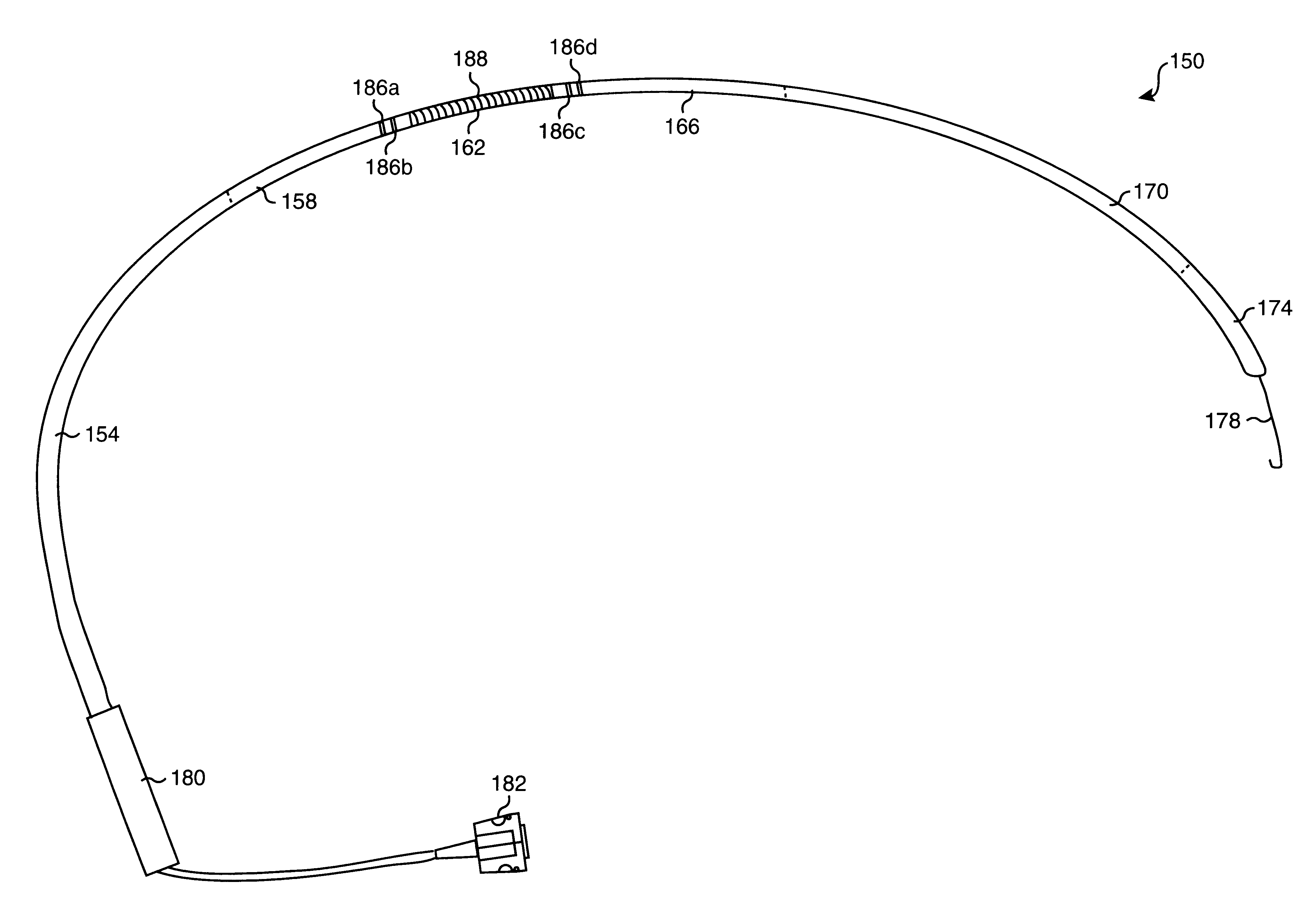
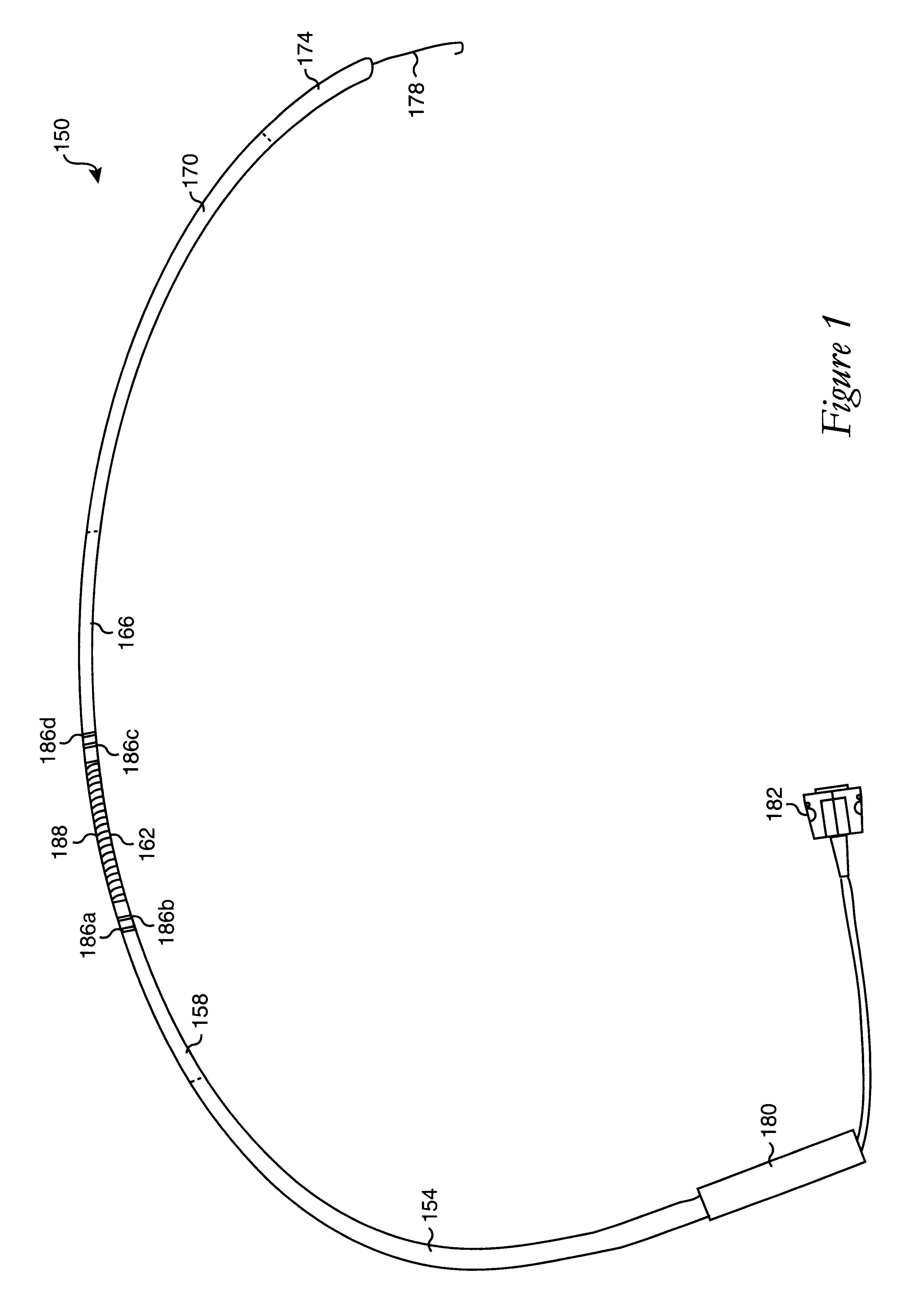
Referring next to FIG. 4a, the internal structure of the interface between a first proximal section of a catheter and a second proximal section of the catheter, e.g., first proximal section 154 and second proximal section 158 of catheter 150 of FIG. 1, will be described in accordance with the present invention. Transmission line 308, which may be a coaxial cable as described above, is disposed within both first proximal section 154 and second proximal section 158. As transmission line 308 is arranged to be coupled to a power source which is typically external to the overall catheter, transmission line 308 extends through substantially the entire length of first proximal section 154. Shrink tubing 330 extends through the entire length of second proximal section 158, and slightly into first proximal section 154. In one embodiment, shrink tubing 330 extends approximately one centimeter past the "transition" between first proximal section 154 and second proximal section 158. Like transm...

second embodiment

FIG. 7 is a diagrammatic longitudinal cross-sectional representation of an antenna portion of a loop catheter formed using polyethylene in accordance with the present invention. It should be appreciated that for illustrative purposes, antenna section 702 and components of the overall loop catheter that are located within antenna section 702, have not been shown to scale. For instance, the relative sizes of some components within antenna section 702 have been exaggerated for illustrative purposes. Antenna section 702 includes a center conductor 704 which is part of a transmission line 708. In one embodiment, transmission line 708 may be a coaxial cable. Transmission line 708 may be coupled to a power supply that is external with respect to the overall catheter. The dimensions of transmission line 708 may vary depending upon the requirements of a particular loop catheter for. By way of example, the outer diameter of transmission line 708 may vary in the range of approximately 0.10 to ...

third embodiment

One suitable handle that may be used in conjunction with a loop catheter is a handle that may be slidably attached and detached from the catheter, as will be described with reference to FIGS. 8a-8d. FIG. 8a is a diagrammatic side-view representation of a detachable handle in accordance with the present invention, while FIG. 8b is a diagrammatic cross-sectional axial representation of the handle. FIGS. 8c and 8d are diagrammatic side-view representations the components of the handle. As shown in FIG. 8a, a handle 804 is arranged to be mounted on a catheter 806 such that handle 804 is aligned along a longitudinal axis of catheter 806. When handle 804 is to be mounted over, or around, catheter 806, catheter is first placed in a groove 820 of base component 812.

Groove 820, as shown in FIG. 8b, is arranged to securely accommodate catheter 806. In other words, groove 820 is sized such that catheter 806 may be held within groove 820 without being damaged. As such, the curvature present in ...


PUM


Abstract

A catheter which may be configured as a loop during an ablation procedure, and a method of use for such a catheter, are disclosed. According to one aspect of the present invention, an ablation catheter includes a flexible distal member arranged to inserted into a first vessel in the body of a patient, and an elongated flexible tubular member with a distal portion which is coupled to a proximal portion of the flexible distal member. The elongated flexible tubular member has a flexibility that is greater than or equal to the flexibility of the flexible distal member. The catheter also includes a transmission line which is at least partially disposed within the elongated flexible tubular member. A proximal end of the transmission line is suitable for connection to an electromagnetic energy source. The catheter further includes a transducer that is coupled to the transmission line, and is arranged to generate an electric field sufficiently strong to cause tissue ablation. In one embodiment, a distal portion of the flexible distal member is arranged to protrude from a second vessel of the body of the patient while at least part of the elongated flexible tubular member is located in a cardiac chamber of the heart of the patient.

Description

1. Field of InventionThe present invention relates generally to ablation catheter systems that use electromagnetic energy in the microwave frequency range to ablate internal bodily tissues. More particularly, the present invention relates to a microwave ablation catheter which may be manipulated to form a loop within a cardiac chamber to facilitate the ablation of cardiac tissue.2. Description of the Related ArtCatheter ablation is a therapy that is becoming more widely used for the treatment of medical problems such as cardiac arrhythmias, cardiac disrhythmias, and tachycardia. Most presently approved ablation catheter systems utilize radio frequency (RF) energy as the ablating energy source. However, RF energy has several limitations which include the rapid dissipation of energy in surface tissues. This rapid dissipation of energy often results in shallow "burns," as well as a failure to access deeper arrhythmic tissues. As such, catheters which utilize electro-magnetic energy in ...

Claims


Application Information

Patent Timeline
IPC IPC(8): A61B18/14
CPCA61B18/1492A61B18/1815A61B2018/141A61B2018/00351A61B2018/00577A61B2018/1846A61B2018/1861
Inventor KNOPP, PETER G.DOWNAR, EUGENEWOODARD, ROBERT E.LARKIN, KEVIN T.NGUYEN, HIEP P. H.
Owner AFX
Why Eureka
Try Eureka