Sounnd source direction detector

A technology of direction detection and sound source, applied in the direction of measuring device, directional device for determining direction, system for determining direction or offset, etc., which can solve problems such as lack of

Active Publication Date: 2009-12-30
PANASONIC CORP
View PDF1 Cites 10 Cited by
  • Summary
  • Abstract
  • Description
  • Claims
  • Application Information

AI Technical Summary

Problems solved by technology

[0007] However, when the sound source direction of the detection sound is obtained from the frequency spectrum of the detection sound after noise cancellation that partially lacks the time portion obtained by the method described in Non-Patent Document 1, it is necessary to reconsider the method described in Patent Document 1. In the cross-correlation calculation method of the method, the processing method of the missing time part due to the influence of noise, and the influence on the result of the sound source direction due to the missing time part of the noise

Method used


Image

  • Sounnd source direction detector
  • Sounnd source direction detector
  • Sounnd source direction detector

Examples


Embodiment 1

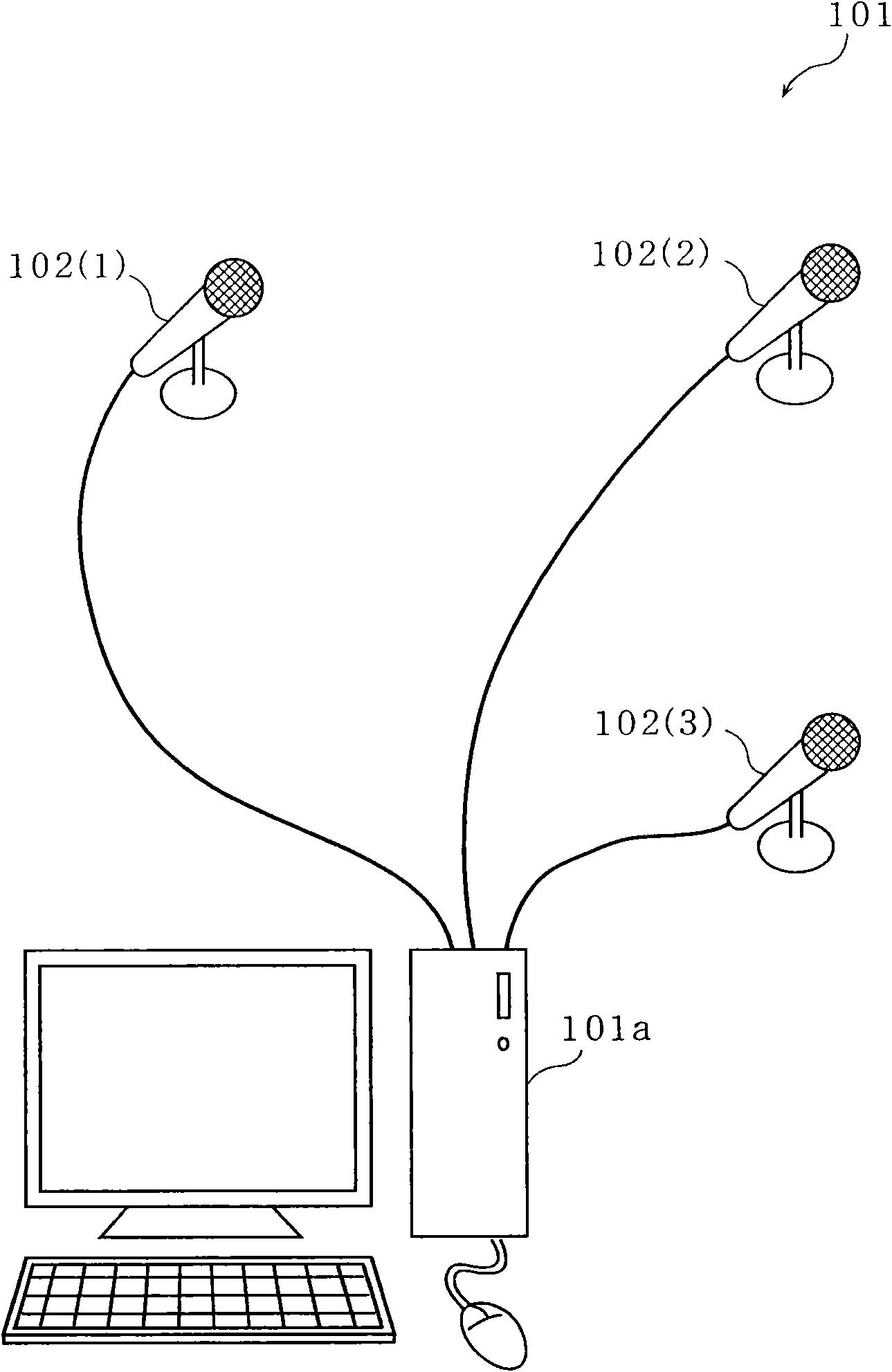
[0109] figure 1 It is an external view of the sound source direction detection device according to the first embodiment of the present invention.

[0110] The sound source direction detection device includes a computer 101a to which three microphones 102(k) (k=1 to 3) are connected.

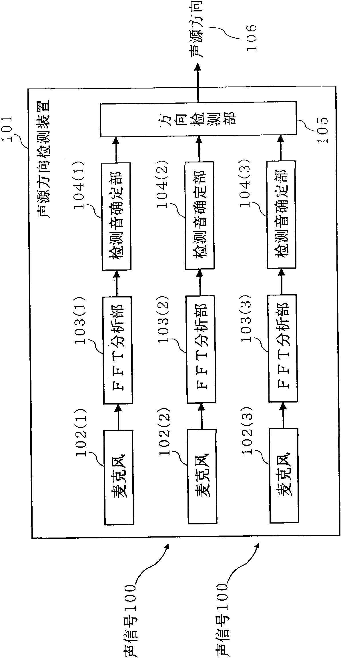
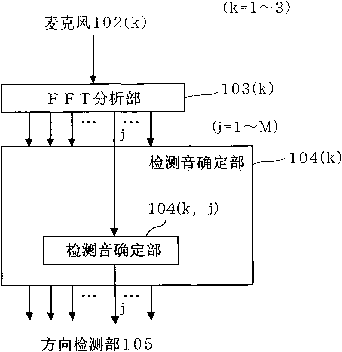
[0111] Figures 2 to 6 It is a block diagram showing the configuration of the sound source direction detection device according to Embodiment 1 of the present invention.

[0112] exist figure 2 Among them, the sound source direction detecting device 101 includes: 3 microphones 102(k) (k=1~3), and 3 fast Fourier transform analysis sections (FFT analysis sections) 103(k) (k=1) corresponding to each microphone. ~3) (equivalent to the analysis unit), three detected sound determination units 104(k) (k=1~3) (equivalent to the detection sound determination unit) corresponding to each microphone, and the direction detection unit 105 (equivalent to the detection unit). FFT analysis part 103 (k) (k=1...

Embodiment 2

[0289] Next, the sound source direction detection device according to the second embodiment will be described. The sound source direction detection device according to the second embodiment is different from the sound source direction detection device according to the first embodiment in that the phase component of the frequency spectrum of the acoustic signal is corrected, and the direction of the sound source is determined using the corrected frequency spectrum.

[0290] Figure 40 ~ Figure 42 It is a block diagram showing the structure of a sound source direction detection apparatus according to Embodiment 2 of the present invention. exist Figure 40 in, with figure 2 The same constituent elements are denoted by the same symbols, and the description thereof will not be repeated.

[0291] exist Figure 40 , the sound source direction detection device 2800 includes three microphones 102(k) (k=1 to 3), and three FFT analysis units 103(k) (k=1 to 3) corresponding to each m...


PUM


Abstract

A sound source direction detector comprises FFT analysis sections (103(1) to 103(3)) for generating a frequency spectrum in at least one frequency band of acoustic signals for each of the acoustic signals collected by two or more microphones arranged apart from one another, detection sound identifying sections (104(1) to 104(3)) for identifying a time portion of the frequency spectrum of a detection sound which obtains a sound source direction from the frequency spectrum in the frequency band, and a direction detecting section (105) for obtaining the difference between the times at which the detection sound reaches the microphones, obtaining the sound source direction from the time difference, the distance between the microphones, and the sound velocity, and outputting it depending on the degree of coincidence between the microphones of the frequency spectrum in the time portion identified by the detection sound identifying sections (104(1) to 104(3)) in a time interval which is the time unit to detect the sound source direction.

Description

technical field [0001] The invention relates to a sound source direction detection device for determining the direction of a sound source under noise, in particular to a sound source direction detection device that reduces the influence of noise and can avoid outputting a wrong direction due to the side effect of eliminating noise. Background technique [0002] As a conventional method for eliminating noise, there is a method of specifying a time portion of the spectrum of the detection sound with little influence of noise from the frequency spectrum of the acoustic signal including the detection sound and noise. (For example, refer to Non-Patent Document 1). [0003] The signal-to-noise ratio (SN ratio), which is the ratio of the spectral powers of the detection sound (S) and the noise (N), is 0 dB or more (the spectral power of the detection sound ≥ the spectral power of the noise), and the noise influence is determined to be small. The time portion of the spectrum of the...

Claims


Application Information

Patent Timeline
Patent Type & Authority Applications(China)
IPC IPC(8): G01S3/808
CPCG01S3/8083
Inventor 芳泽伸一中藤良久
Owner PANASONIC CORP
Why Eureka
Try Eureka