Eureka AIR delivers breakthrough ideas for toughest innovation challenges, trusted by R&D personnel around the world.

Fuel injection valve and fuel injection device

a fuel injection valve and fuel injection technology, which is applied in the direction of machines/engines, mechanical equipment, instruments, etc., can solve the problems of difficult to accurately measure the pressure of fuel, and achieve the effects of improving the accuracy of pressure sensing, facilitating formation, and facilitating thickness control

Active Publication Date: 2013-11-26
DENSO CORP +1
View PDF61 Cites 9 Cited by
  • Summary
  • Abstract
  • Description
  • Claims
  • Application Information

AI Technical Summary

Benefits of technology

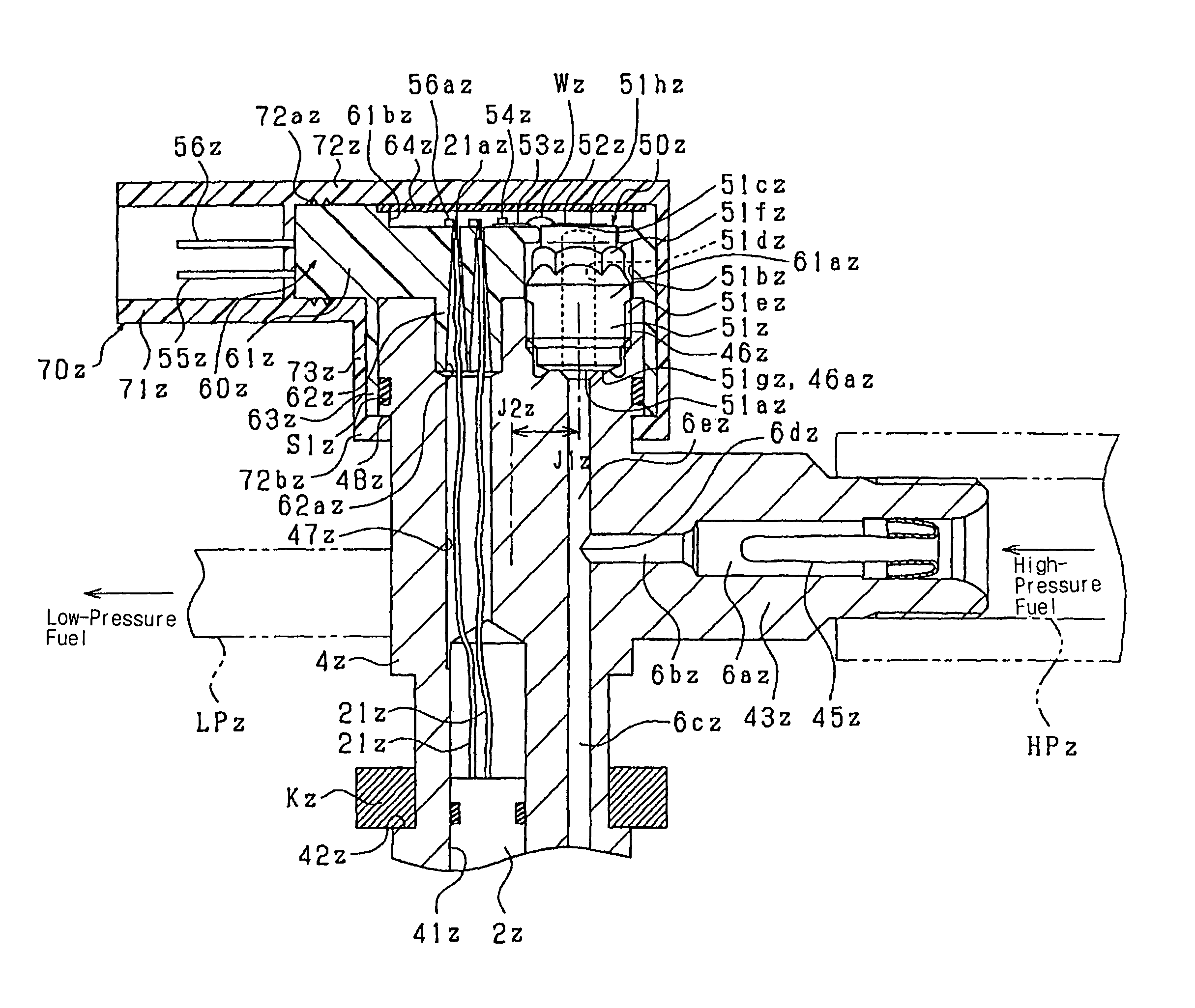
[0029]This permits a loss of propagation of inner stress in the body resulting from thermal expansion / contraction to the elastic body to be increased because the elastic body is constructed to be separate from the body. Specifically, the elastic body is made to be separate from the body, thus reducing the adverse effects of the distortion of the body on the elastic body. Therefore, the invention in which the sensing device is installed on the elastic body constructed to be separate from the body reduces the adverse effects of the distortion of the body on the elastic body as compared with when the elastic body is attached directly to the body. This enables the fuel pressure sensor to be installed in the fuel injection valve while avoiding a decrease in accuracy in measuring the pressure of fuel.
[0066]The second diaphragm defined by the thin-walled portion is disposed in the branch path diverging from the fluid path, thus resulting in ease of formation of the second diaphragm as compared with when the diaphragm is disposed directly in the injector wall near the fluid path. This also results in ease of controlling the thickness of the second diaphragm, which improves the pressure sensing accuracy. It also possible to measure the pressure in a plurality of channels, which enables an output signal from the pressure sensing portion, as described in an example embodiment of the invention, to be outputted redundantly.

Problems solved by technology

A fuel pressure sensor (i.e., a rail pressure sensor) installed directly in a common rail (i.e., an accumulator vessel) to measure the above change in pressure of the fuel has a difficulty in measuring the pressure of the fuel accurately because the change in pressure of fuel arising from the spraying of the fuel is absorbed within the common rail.

Method used


Image

  • Fuel injection valve and fuel injection device
  • Fuel injection valve and fuel injection device
  • Fuel injection valve and fuel injection device

Examples


first embodiment

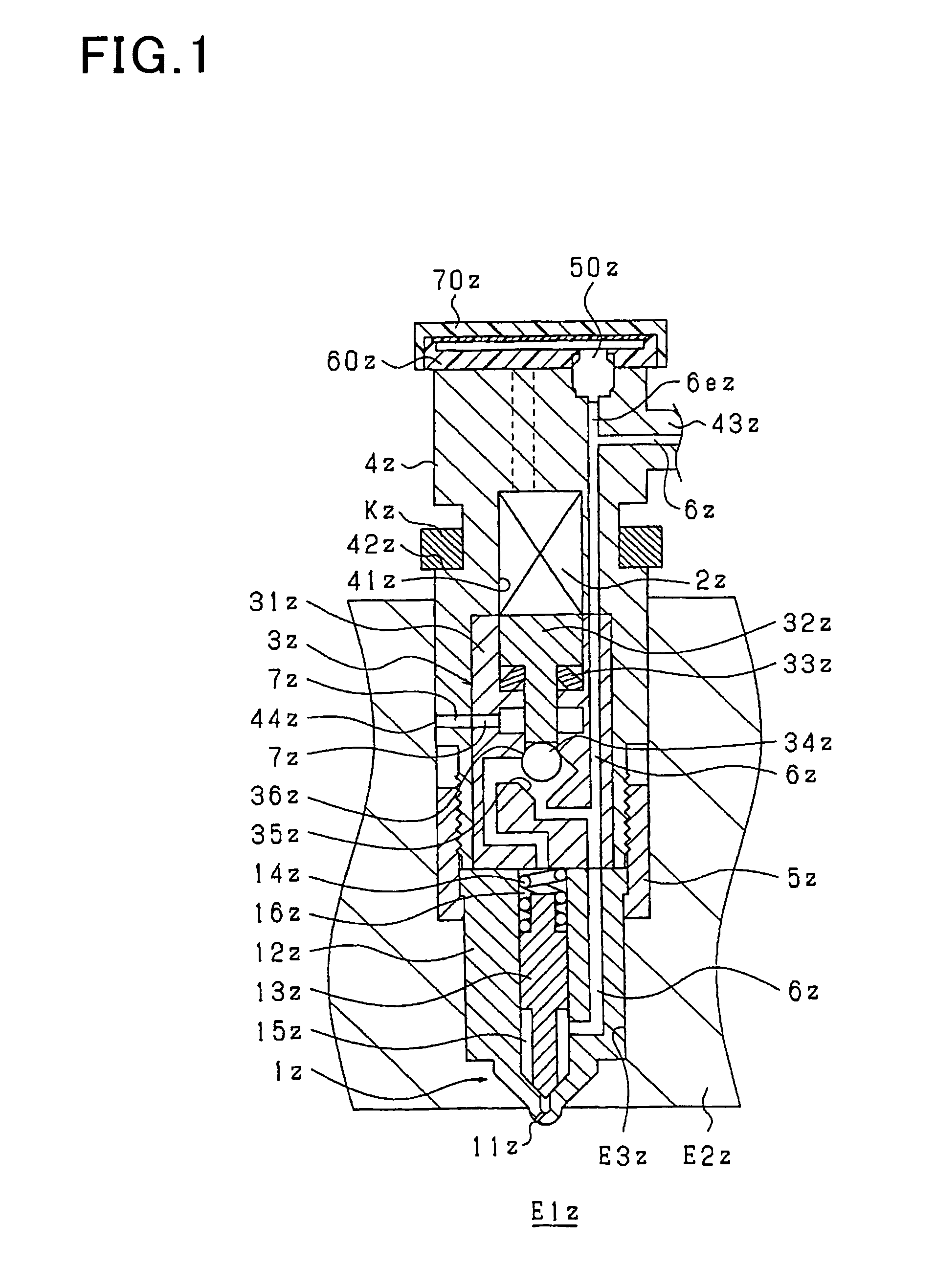
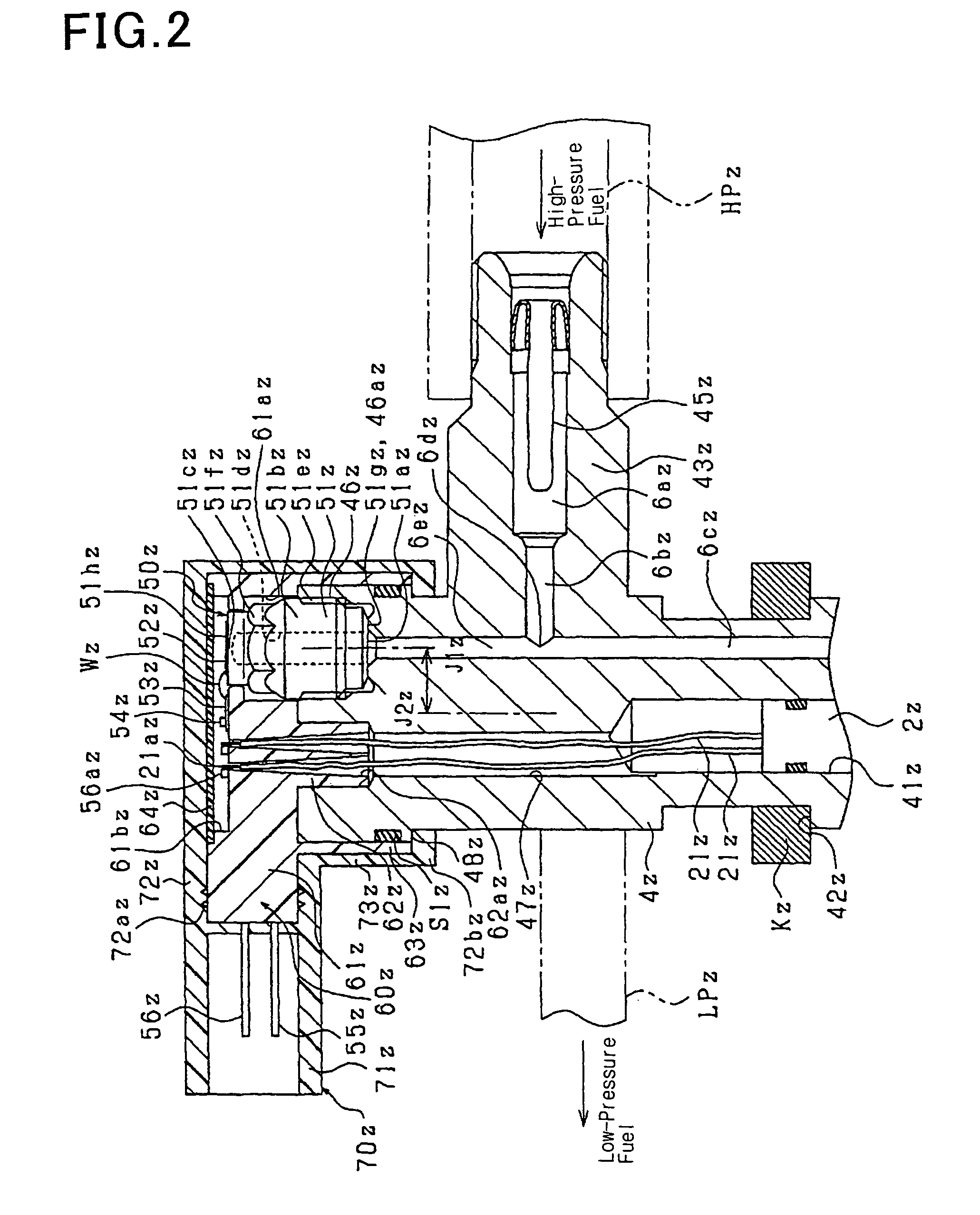
[0236]The first embodiment of the invention will be described using FIGS. 1 and 2. FIG. 1 is a schematic sectional view which shows an outline of inner structure of an injector (i.e., a fuel injection valve) according to this embodiment. FIG. 2 is an enlarged view for explaining FIG. 1 in detail.

[0237]First, a basic structure and operation of the injector will be described based on FIG. 1. The injector is to spray high-pressure fuel, as stored in a common rail (not shown), into a combustion chamber E1z formed in a cylinder of an internal combustion diesel engine and includes a nozzle 1z for spraying the fuel when the valve is opened, a piezo actuator 2z (opening / closing mechanism) which expands or contracts when charged or discharged electrically, and a back pressure control mechanism 3z (opening / closing mechanism) which is driven by the piezo actuator 2z to control the back pressure acting on the nozzle 1z.

[0238]The nozzle 1z is made up of a nozzle body 12z in which spray holes 11...

second embodiment

[0278]The first embodiment is so designed that the installation of the fuel pressure sensor 50z in the injector body 4z is achieved by fitting it into the injector body 4z from outside the axial line J2z of the cylindrical injector body 4z. In contrast to this, the embodiment of FIG. 3 is designed to achieve the installation from radially outside the cylindrical body 4z. Specifically, the cylindrical injector body 4z has formed in an outer circumferential surface a recess 461z into which the cylinder 51bz of the stem 51z of the fuel pressure sensor 50z is to be fitted. Therefore, a sealing surface 461az of the body 4z which creates the metal-to-metal touch seal between itself and the stem 51z is oriented so as to expand in parallel to the axial line J2z.

[0279]The high-pressure port 43z of the injector of the first embodiment is so oriented as to join the high-pressure pipe HPz in the radial direction of the injector. The high-pressure port 431z of this embodiment is so oriented as ...

third embodiment

[0282]The second embodiment has the branch path 6ez which diverges from the high-pressure path 6az to deliver the high-pressure fuel to the fuel pressure sensor 50z. In this embodiment of FIG. 4, the branch path 6ez is omitted, while the fuel pressure sensor 50z is installed directly in the high-pressure path 6az through which the fuel flows to the spray hole 11z.

[0283]Specifically, the structure in which the stem 51z is made up of the cylindrical portion 51bz and the diaphragm 51cz is omitted. Instead, the top end portion 511az of the stem 51z protrudes into the high-pressure path 6az, so that the tope end portion 511az is positioned inside the high-pressure path 6az. The strain gauge 52z is affixed to the inside of the top end portion 511az (i.e., inside the stem 51z) and converts the degree of strain occurring in the top end portion 511az into an electric signal to output it as a measured pressure signal.

[0284]In the above embodiments, the sealing surface 46az of the injector bo...


PUM


Abstract

It is equipped with an injector body 4z which has formed therein high-pressure paths 6az, 6bz, and 6cz through which high-pressure fuel flows to a spray hole and stores therein a piezo-actuator 2z (i.e., an opening / closing mechanism) and a back-pressure control mechanism 3z (i.e., an opening / closing mechanism) which open or close the spray hole, a stem 51z (i.e., an elastic body) which is installed in said body 4z and elastically deformed when subjected to pressure of the high-pressure fluid, and a strain gauge 52z (i.e., a sensing device) which converts the degree of strain occurring at the stem 51z into an electric signal and outputs it as a measured-pressure signal. Specifically, the stain gauge 52z is installed on the stem 51z that is constructed as being separate from the body 4z.

Description

[0001]This application is the U.S. national phase of International Application No. PCT / JP2008 / 069419 filed 27 Oct. 2008 which designated the U.S. and claims priority to JP Patent Application Nos. 2007-286520 filed 2 Nov. 2007, 2007-289072 filed 6 Nov. 2007, 2008-037846 filed 19 Feb. 2008 and 2008-243807 filed 24 Sep. 2008, the entire contents of each of which are hereby incorporated by reference.TECHNICAL FIELD[0002]The present invention relates generally to a fuel injection valve which is installed in an internal combustion engine to spray fuel from a spray hole and a fuel injection device.BACKGROUND ART[0003]In order to ensure the accuracy in controlling output torque of internal combustion engines and the quantity of exhaust emissions therefrom, it is essential to control a fuel injection mode such as the quantity of fuel to be sprayed from a fuel injection valve or the injection timing at which the fuel injection valve starts to spray the fuel. Accordingly, there have been propo...

Claims


Application Information

Patent Timeline
Patent Type & Authority Patents(United States)
IPC IPC(8): F02M51/00G01M15/00
CPCF02M47/027F02M57/005F02M63/0026G01L23/18F02D2200/0602F02D2400/08F02M51/005F02M2200/24
Inventor KONDO, JUNTAGUCHI, TOORUARIKAWA, FUMIAKIYAMANAKA, AKITOSHI
Owner DENSO CORP
Why Eureka
Eureka Blog
Learn More