Self-moving belt machine tail part

A belt conveyor, self-moving technology, applied in conveyors, conveyor objects, cleaning devices, etc., can solve the problems of low degree of mechanization, high labor intensity and labor, and achieve the effect of solving adjustment difficulties.

Inactive Publication Date: 2010-01-13
SHANXI DONGHUA MACHINERY
View PDF0 Cites 12 Cited by
  • Summary
  • Abstract
  • Description
  • Claims
  • Application Information

AI Technical Summary

Benefits of technology

The technical effect of this new design is that it includes both a fixation system for easy removal from its original position after being attached or connected to another object while also having some type of antimigration feature where if there are any issues during use. This makes it easier to maintain accurate measurements over time without requiring frequent recalibration by experts at different locations around the world.

Problems solved by technology

This patented technical problem addressed in this patents relates to how to connect or disconnect an end portion between two parts called a linkage that are used during mineral operations such as coal production. Existing methods require manual effort and slow down machinery due to their high cost and complexity.

Method used


Image

  • Self-moving belt machine tail part

Examples


Embodiment Construction

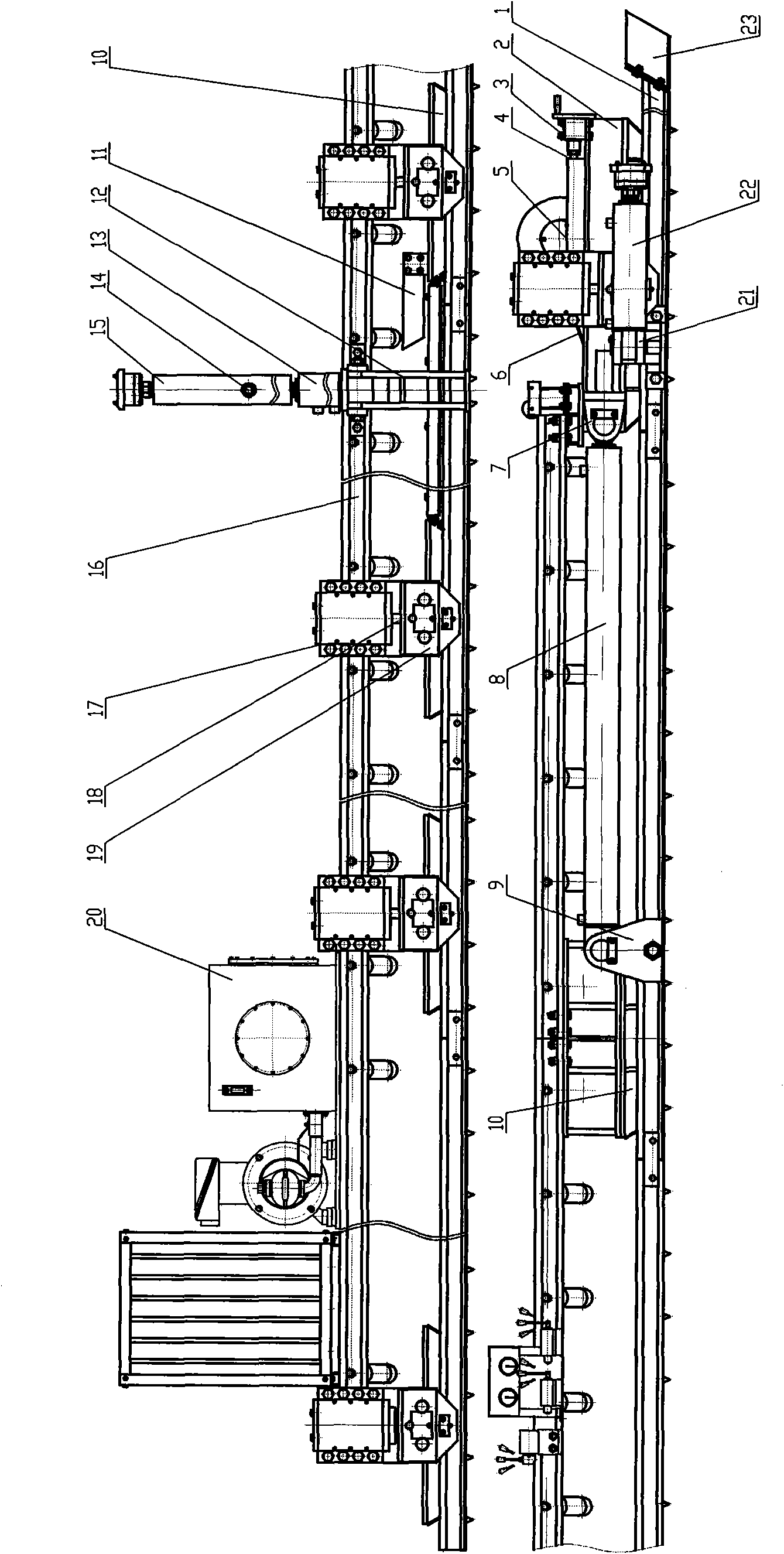
[0021] The present invention comprises machine tail 2, middle frame 10, upper travel guide rail 16, hydraulic system 20, also comprises lifting mechanism, pushing cylinder 8, lower travel guide rail 1, and lifting mechanism is composed of lifting cylinder 18 and support cylinder frame 17, two-way travel guide wheel frame 19, the tail 2 and the middle frame 10 are respectively equipped with a support cylinder frame 17, the two-way travel guide wheel frame 19 is installed on the lower travel guide rail 1, and the lifting cylinder 18 is connected to the support cylinder frame 17 and the two-way travel guide wheel frame 19 respectively, The following walking guide rail 1 is installed on the tail both sides of the machine, and the bottom surface has a floor to hold, and the oil cylinder 8 is installed between the following walking guide rail 1 and the machine tail. When moving, the machine tail can be raised and seated on the lower walking guide rail 1, and the machine tail is moved...


PUM


Abstract

The invention relates to a moving device of a belt machine, in particular a self-moving belt machine tail part which comprises a machine tail, a middle stand, an upper walking guide track and a hydraulic system and is characterized by also comprising a lifting mechanism, a pushing cylinder and lower walking guide tracks, wherein the lifting mechanism comprises a lifting cylinder, a supporting cylinder frame and a bidirectional walking guide wheel frame; the machine tail and the middle stand are respectively provided with a supporting cylinder frame, the bidirectional walking guide wheel frame is arranged on the lower walking guide tracks, the lifting cylinder and the frames are respectively connected with the bidirectional walking guide wheel frame, the lower walking guide tracks are arranged at two sides of the machine tail part, a ground grasping plate is arranged on the bottom surface of the machine tail part, and the pushing cylinder is arranged between the lower walking guide tracks and the machine tail part. The moving device can not only move by self with maximum movement of 2m every time, but also can fix by self so as to prevent machine tail malposition in the conveying operation; an offset-regulating device of a machine tail roller is adopted to solve the offset of the machine tail roller; and a fixing mechanism is adopted to solve that the regulation is difficult when the machine tail is fixed.

Description


Claims


Application Information

Patent Timeline
Owner SHANXI DONGHUA MACHINERY
Why Eureka
Try Eureka