A high-pressure and high-speed damper precise adjustment mechanism

An adjustment mechanism, high-speed technology, applied in valve details, mechanical equipment, engine components, etc., to achieve high-precision adjustment

Active Publication Date: 2020-02-11
NORTHEASTERN UNIV LIAONING
View PDF6 Cites 0 Cited by
  • Summary
  • Abstract
  • Description
  • Claims
  • Application Information

AI Technical Summary

Problems solved by technology

[0004] The invention provides a high-pressure high-speed damper precise adjustment mechanism, which solves the problem of precise and stable control of the air volume of large induced draft fans, large compressors, steam turbines, blowers and aeroengine dampers

Method used


Image

  • A high-pressure and high-speed damper precise adjustment mechanism
  • A high-pressure and high-speed damper precise adjustment mechanism
  • A high-pressure and high-speed damper precise adjustment mechanism

Examples


Embodiment Construction

[0015] The present invention is further described below in conjunction with embodiment.

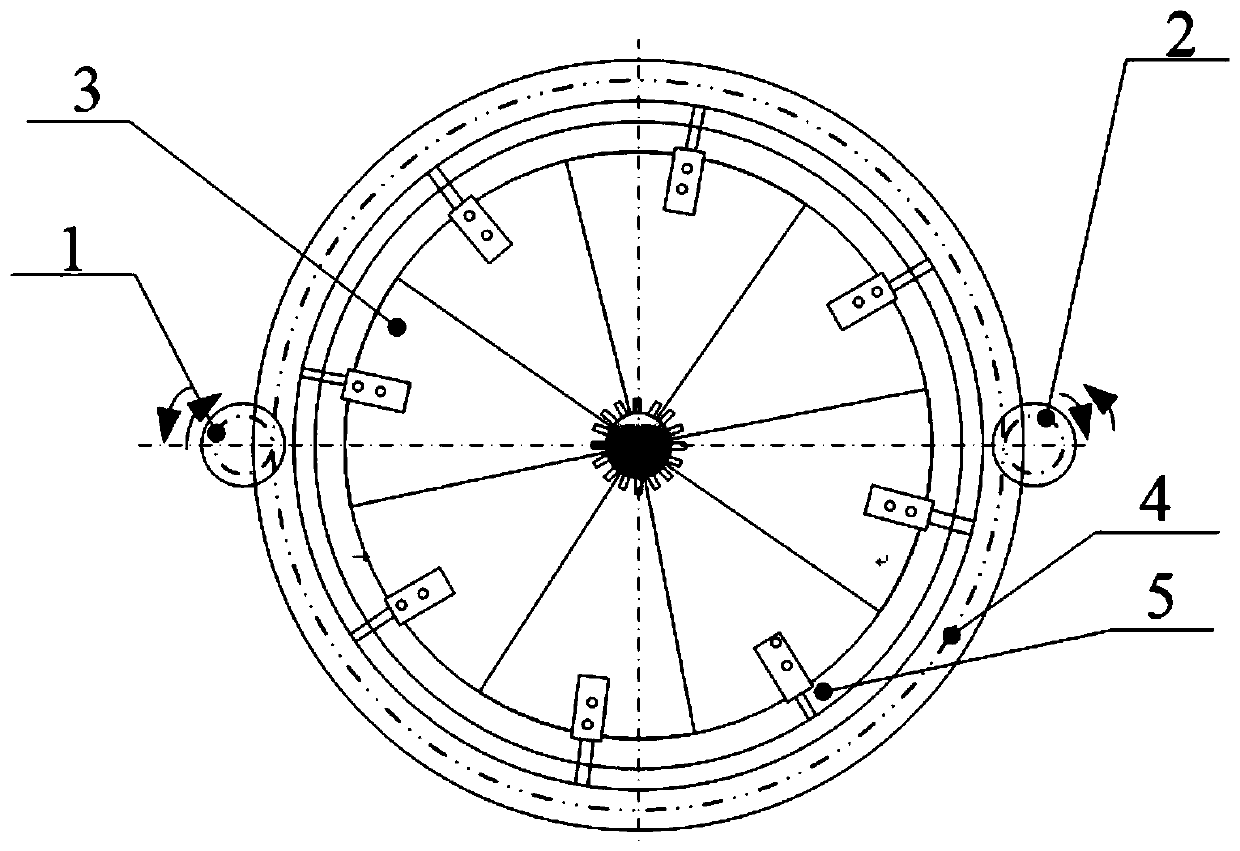
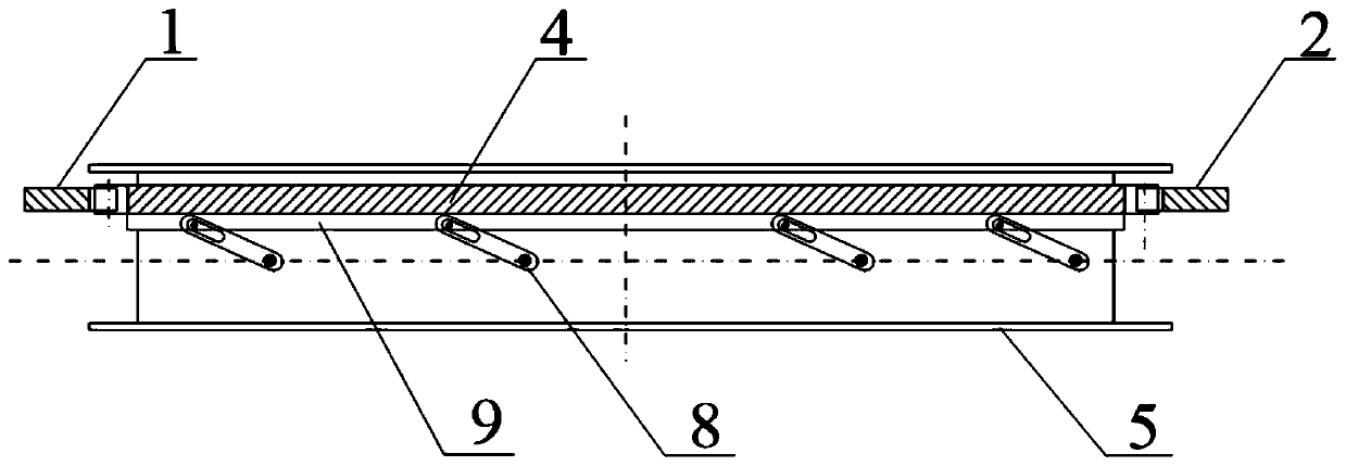
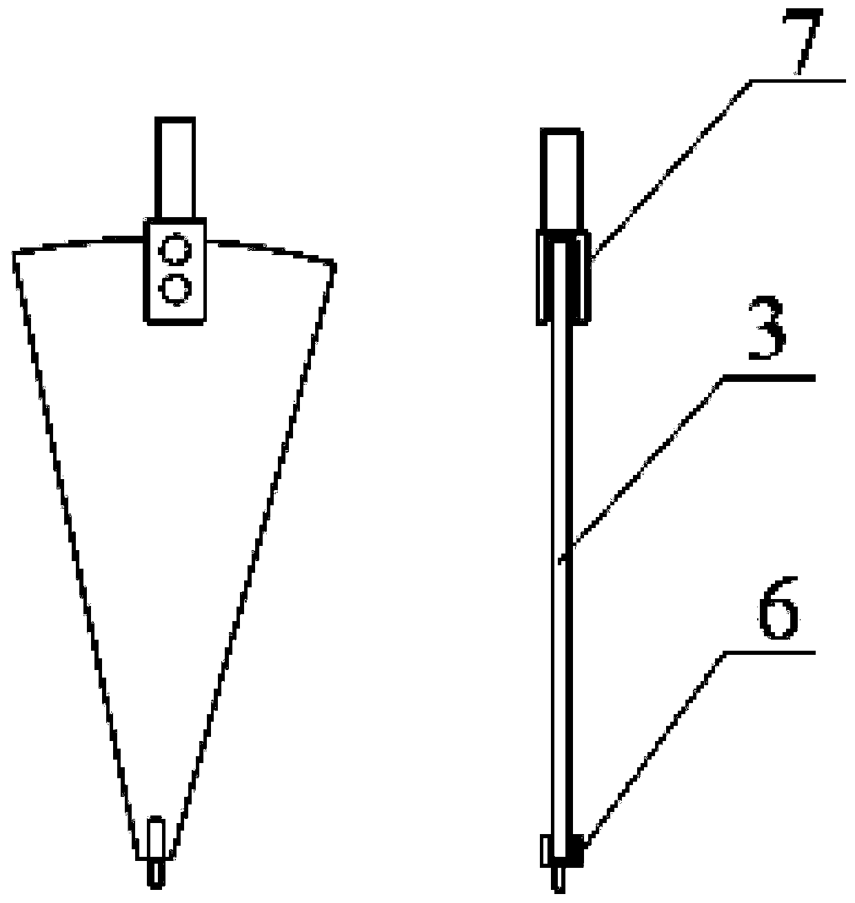
[0016] A high-pressure high-speed damper precision adjustment mechanism, including pinion A1, pinion B2, large gear ring 4, blade 3, fixed ring 5, transverse connecting rod 8, flange 9, connecting small shaft A6 and connecting small shaft B7.

[0017] The fixed ring 5 covers the large gear ring 4, and the outer side of the large gear ring 4 fixes the pinion A1 and the pinion B2 symmetrically along the diameter, and the two small gears mesh with the large gear ring 4 respectively. The motor drives the large gear ring 4 to rotate; the large gear ring 4 and the flange 9 are fixed together, the flange 9 is located on the outer wall of the fixed ring 5, the large gear ring 4 drives the flange 9 to rotate, and the flange There are 2N protrusions on the outer side of 9, and the protrusions are connected with the oval hole of the transverse connecting rod 8; one end of the transverse connecting r...


PUM


Abstract

The invention belongs to the technical field of air door adjustment, and particularly relates to an accurate high-pressure and high-speed air door adjusting mechanism. The adjusting mechanism comprises a small gear A, a small gear B, a large gear ring, blades, a fixing ring, transverse connecting rods, a flange plate, connecting small shafts A and connecting small shafts B. The fixing ring is sleeved with the large gear ring. The small gear A and the small gear B are symmetrically fixed to the outer side of the large gear ring along the diameter. The large gear ring and the flange plate are fixed together. The flange plate is located on the outer wall of the fixing ring. One end of each transverse connecting rod is provided with a through oval hole, and the other end of each transverse connecting rod is fixedly connected with the top end of the corresponding connecting small shaft B. The connecting small shafts B penetrate through the fixing ring, the lower ends of the connecting smallshafts B are fixed to the arc edges of the blades, and the triangular ends of the blades are fixed to the connecting small shafts A. The connecting small shafts A of the blades are fixed to the circle center of the fixing ring, and the circular face of the fixing ring is formed through the blades. The air door adjusting mechanism capable of running in the high-pressure and high-speed states is provided, meanwhile, high-precision adjustment of an air door can be achieved, and it can be guaranteed that the blades do not vibrate after being positioned.

Description

technical field [0001] The invention belongs to the technical field of damper adjustment, and in particular relates to a high-pressure and high-speed damper precision adjustment mechanism. Background technique [0002] In the engineering technology industry, it is often necessary to use fans with adjustable dampers as ventilation equipment. The traditional air door mechanism usually uses a single blade for adjustment to control the opening and closing of the air door. By rotating the blade, the angle of the blade can be adjusted to adjust the air volume. Accuracy, and the working point of the damper drifts, and it is difficult to self-lock. [0003] Another kind of damper adjustment mechanism currently used by various manufacturers is the petal-type leaf-type adjustment door. Compared with the single-blade adjustment door, this kind of adjustment accuracy is much improved, but the damper needs to be adjusted manually by using screws or other components. Positioning, such a...

Claims


Application Information

Patent Timeline
Patent Type & Authority Patents(China)
IPC IPC(8): F16K31/04
CPCF16K31/043
Inventor 张学良胡文海林瑞鑫王志辉李超马辉闻邦椿
Owner NORTHEASTERN UNIV LIAONING
Why Eureka
Try Eureka