A wavelength coated end cap assembly for suppressing stimulated Raman scattering and application thereof

A technology of stimulated Raman scattering and end caps, which is applied to the structure/shape of the active medium, lasers, phonon exciters, etc., to achieve the effect of suppressing the effect of stimulated Raman scattering

Pending Publication Date: 2019-01-04
NAT UNIV OF DEFENSE TECH
View PDF5 Cites 2 Cited by
  • Summary
  • Abstract
  • Description
  • Claims
  • Application Information

AI Technical Summary

Problems solved by technology

Therefore, there is currently no bidirectional fiber end cap capable of both feedback and suppression of stimulated Raman scattering effects

Method used


Image

  • A wavelength coated end cap assembly for suppressing stimulated Raman scattering and application thereof
  • A wavelength coated end cap assembly for suppressing stimulated Raman scattering and application thereof
  • A wavelength coated end cap assembly for suppressing stimulated Raman scattering and application thereof

Examples


Embodiment 1

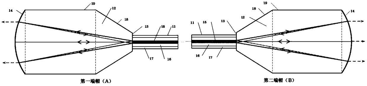
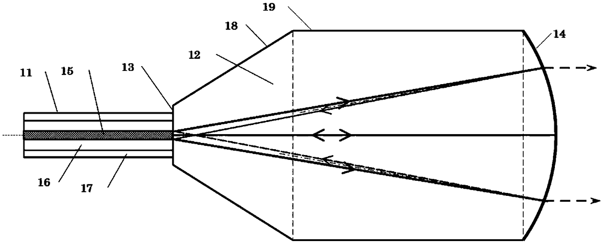
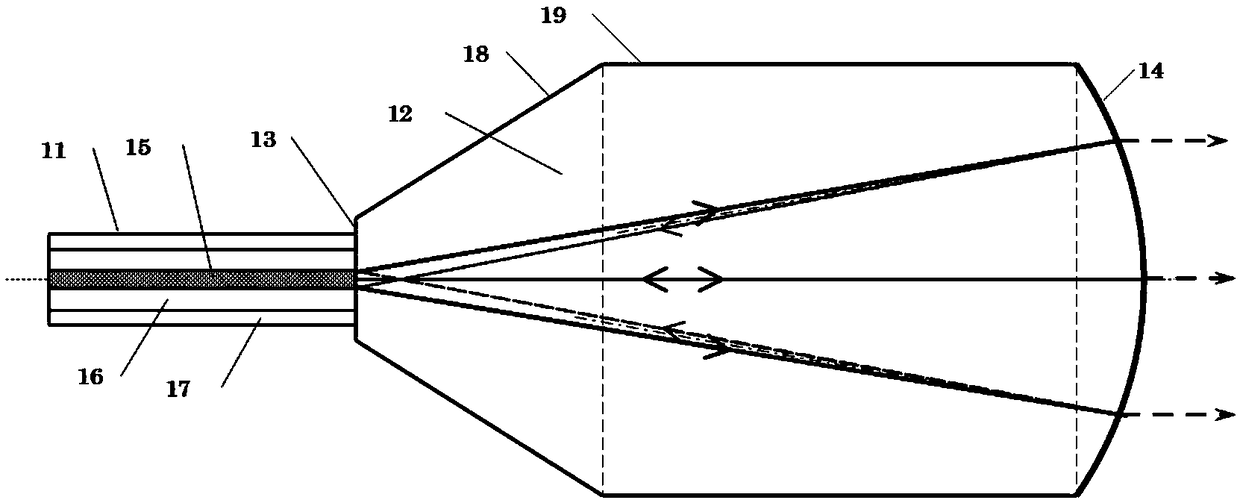
[0026] A wavelength-coated end cap group that suppresses stimulated Raman scattering, the structure diagram is as follows figure 1 As shown, including a first end cap A and a second end cap B, the structure of the first end cap A is as figure 2 As shown, the structure of the second end cap B is image 3 As shown, it can be seen that both the first end cap A and the second end cap B include an optical fiber 11 and a specially designed quartz block 12. The optical fiber 11 may be a double-clad optical fiber, consisting of a core 15 and an inner cladding. 16. Composed of outer cladding layer 17, or single-clad fiber, composed of core 15 and cladding layer 17; quartz block 12 is formed by connecting circular truncated cone 18, cylinder 19 and output curved body 14 with the same connection end face size in sequence The output end face of the optical fiber 11 and the input end face of the quartz block 12 (that is, the smaller end face of the round table 18) are welded to form an inter...

Embodiment 2

[0028] An all-fiber oscillator employing wavelength-coated end caps that suppress stimulated Raman scattering. Its structure is as follows Figure 4 As shown, it includes a first end cap A, a second end cap B, a rare earth-doped particle gain fiber 23, a pump signal combiner 24, a fiber-coupled semiconductor laser 25, a signal energy transmission fiber 26, and a pump energy transmission fiber 27 The signal energy transmission fiber 26 connects the first end cap A, the pump signal combiner 24, the rare earth-doped particle gain fiber 23 and the second end cap B in sequence; the pump signal combiner 24 has one or Multiple pump arms, one signal input arm, and one signal output arm; a group of fiber-coupled semiconductor lasers 25 are connected to the pump arms of the pump signal combiner 24 through the pump energy transmission fiber 27; the first end cap The structure of A and the second end cap B is as shown in embodiment 1, and the components of the first end cap A and the secon...


PUM


Abstract

A wavelength-coated end cap set for suppressing stimulated Raman scattering comprises a first end cap and a second end cap, both end caps comprising an optical fiber and a quartz block; The quartz block is formed by connecting a circular table with the same end face size, a cylinder and an output curved surface in turn; One end face of the optical fiber is welded with the smaller end face of the circular table to form an interface; The extension line of the core line of the optical fiber is the center line of the circular table, the cylinder and the output curved surface; and the extension line of the core line of the optical fiber is the center line of the circular table and the output curved surface. The curved surface of the output curved surface is coated with film on the curved surface of the output curved surface with the intersection of the core extension line of the optical fiber and the interface as the spherical center and the sum of the lengths of the quartz block centerlinein the circular table, the cylinder and the output curved surface as the radius of curvature. The coating film on the surface of the first end cap is highly reflective at 900 nm to 1000 nm and 1060 to 1100 nm; and the coating film on the curved surface of the second end cap is lowly reflective on the 1060-1100 nm band, and fully transmissive on the other bands.

Description

Technical field [0001] The present invention generally relates to the field of fiber lasers, in particular to a wavelength coating end cap group for suppressing stimulated Raman scattering and its application. Background technique [0002] High-power fiber lasers have a wide range of applications in laser cutting, laser cladding, 3D printing and other fields. In recent years, with the increase in the power of double-clad fiber manufacturing technology and high-brightness semiconductor lasers, the output power of single-channel high-power fiber lasers has been rapidly developed, from 100 watts in the early 21st century to the current 10 kilowatts. With the continuous improvement of fiber laser output power, stimulated Raman scattering has become one of the main limiting factors limiting the output power of high-power fiber lasers. Traditional methods to suppress SRS include shortening the length of the gain fiber and increasing the area of ​​the mode field. Then, as the output p...

Claims


Application Information

Patent Timeline
Patent Type & Authority Applications(China)
IPC IPC(8): H01S3/067G02B6/26
CPCH01S3/06708G02B6/262
Inventor 叶云王小林许晓军张汉伟奚小明史尘陈子伦王泽锋
Owner NAT UNIV OF DEFENSE TECH
Why Eureka
Try Eureka