
Method for reducing return water temperature of heat supply pipeline

A technology of return water temperature and heat supply pipes, which is applied in the energy field, can solve the problems of primary network supply and temperature difference limitation of return water, and achieve the effects of reducing energy consumption of primary network transmission and distribution, reducing return water temperature, and expanding the heating radius

Active Publication Date: 2011-06-29
TSINGHUA UNIV +1
View PDF0 Cites 4 Cited by
  • Summary
  • Abstract
  • Description
  • Claims
  • Application Information

AI Technical Summary

Problems solved by technology

At present, the temperature of the hot water supply and return water in the primary network of the central heating system is generally about 130°C / 70°C. Due to the limitation of heat requirements of the heating users, the return water temperature of the primary network is higher than the return water temperature of the secondary network. Therefore, the temperature difference between primary network supply and return water is limited

Method used


Image

  • Method for reducing return water temperature of heat supply pipeline
  • Method for reducing return water temperature of heat supply pipeline
  • Method for reducing return water temperature of heat supply pipeline

Examples


Embodiment 1

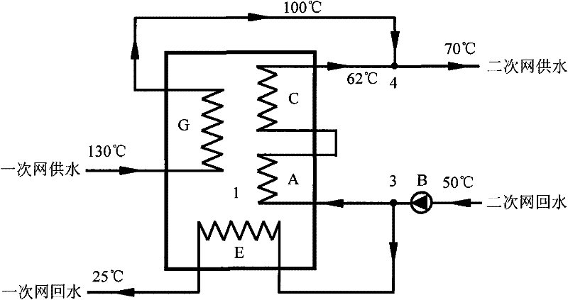
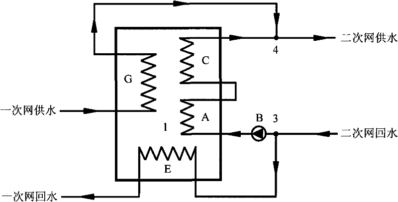
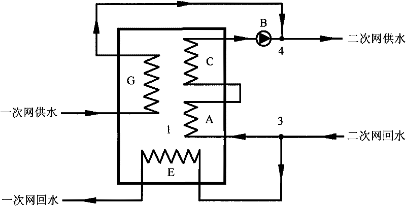
[0021] Such as figure 1 As shown, the waterway system is divided into a primary network hot water pipeline and a secondary network hot water pipeline, and the primary network hot water pipeline and the secondary network hot water pipeline are directly connected by means of an absorption heat pump / refrigerator 1 , by connecting the pipeline to reduce the return water temperature of the heating pipeline of the primary network.

[0022] In actual operation, the 130°C hot water on the high temperature side of the primary network pipeline first enters the generator G of the absorption heat pump / refrigerator 1 as a driving heat source, heats the lithium bromide solution, and drives the absorption heat pump / refrigerator 1 to realize heat transfer from a low temperature heat source to a high temperature The transfer of the heat source, after cooling down to 100°C in the generator G, flows out of the generator G and enters the secondary network. The 50°C return water of the secondary n...

Embodiment 2

[0026] Such as Image 6 As shown, the waterway system is divided into the hot water pipeline of the primary network and the hot water pipeline of the secondary network. With the help of the absorption heat pump / refrigerator 1 and the water-to-water heat exchanger 2, the primary network and the secondary network are indirectly connected. Connect pipes to lower the return temperature of the primary heating circuit.

[0027] In actual operation, hot water at 130°C on the high-temperature side of the primary network first enters generator G of absorption heat pump / refrigerator 1 as a high-level heat source, heats the lithium bromide solution, and flows out of generator G when the heat release cools down to 90°C. The hot water enters the water-to-water heat exchanger 2 as a heating source, heats the return water of the secondary network, and flows out of the water-to-water heat exchanger 2 when the temperature drops to 55°C, and returns to the absorption heat pump / refrigerator 1, w...


PUM


Abstract

The invention discloses a method for reducing return water temperature of a heat supply pipeline, which belongs to the technical field of energy. A waterway system of the heat supply pipeline is divided into a primary network hot water pipeline and a secondary network hot water pipeline, and the return water temperature of a primary network of the heat supply pipeline of a centralized heat supplysystem is reduced with the help of an absorption heat pump / refrigerator and a water-water heat exchanger or the single absorption heat pump / refrigerator, thereby increasing the temperature differencebetween supply water and return water of the primary network, wherein, when the single absorption heat pump / refrigerator is used, the primary network hot water pipeline and the secondary network hot water pipeline are connected by adopting the direct connection way, when the absorption heat pump / refrigerator and the water-water heat exchanger are used, the primary network hot water pipeline and the second network hot water pipeline are connected by adopting the indirect connection way. The method can greatly reduce the return water temperature of the primary network pipeline, increase the temperature resistance between the supply water and the return water of the primary network, further reduce the initial development of the heat supply pipeline and the transmission and distribution energy consumption of the primary network to a greater extent, reduce the operation cost of centralized heat supply and enlarge the heat supply radius of a heat source for heat supply.

Description

technical field [0001] The invention belongs to the field of energy technology, in particular to a method for reducing the return water temperature of a heat supply pipeline. Background technique [0002] With the continuous expansion of city scale, high-temperature hot water generated by centralized heat sources often needs to be transported over a long distance to reach heat users, and the energy consumption of pipeline network transmission and distribution is relatively large. With the development of urban economy and population growth, the heating load of the city increases sharply, and the existing heating pipe network can hardly meet the heat load demand of heat users according to the conventional operation mode. Under the same hot water flow rate and heating temperature, reducing the return water temperature and increasing the temperature difference between hot water supply and return water can increase the heating load and reduce the hot water consumption of the pipe...

Claims


Application Information

Patent Timeline
Patent Type & Authority Patents(China)
IPC IPC(8): F24D3/18F24D3/02F24D3/10
CPCY02B30/12
Inventor 付林孙方田张世钢江亿罗勇肖常磊胡鹏
Owner TSINGHUA UNIV
Learn More