
Fuel gas combined heat and power generation heating supply system based on absorption-type heat exchange

A technology for combined heat and power generation and heating systems, applied in heating systems, hot water central heating systems, heating fuels, etc. In order to reduce the temperature difference between the return water of the heating network and the temperature difference between the supply and return water, improve energy utilization efficiency, and reduce the pipe diameter

Inactive Publication Date: 2015-10-07
ZHONGNENG SHIHUA BEIJING ENERGY SAVING SCI & TECH
View PDF8 Cites 5 Cited by
  • Summary
  • Abstract
  • Description
  • Claims
  • Application Information

AI Technical Summary

Problems solved by technology

[0003] Although it has certain advantages, there are still some problems to be solved in the conventional gas-fired cogeneration system: 1) The heat transfer temperature difference between the primary and secondary grids at the thermal station and the steam and water at the heat source is very large, resulting in a large irreversible heat loss
However, in the field of district heating, the return water temperature of the heating network is generally above 50-60°C, which is higher than the dew point of flue gas condensation, and effective recovery of flue gas condensation heat cannot be realized.
3) In addition, the current heat and power cogeneration ratio is low, generally 0.6-0.8

Method used


Image

  • Fuel gas combined heat and power generation heating supply system based on absorption-type heat exchange

Examples


Embodiment Construction

[0011] The following will clearly and completely describe the technical solutions in the embodiments of the present invention with reference to the accompanying drawings in the embodiments of the present invention. Obviously, the described embodiments are only some, not all, embodiments of the present invention. Based on the embodiments of the present invention, all other embodiments obtained by persons of ordinary skill in the art without making creative efforts belong to the protection scope of the present invention.

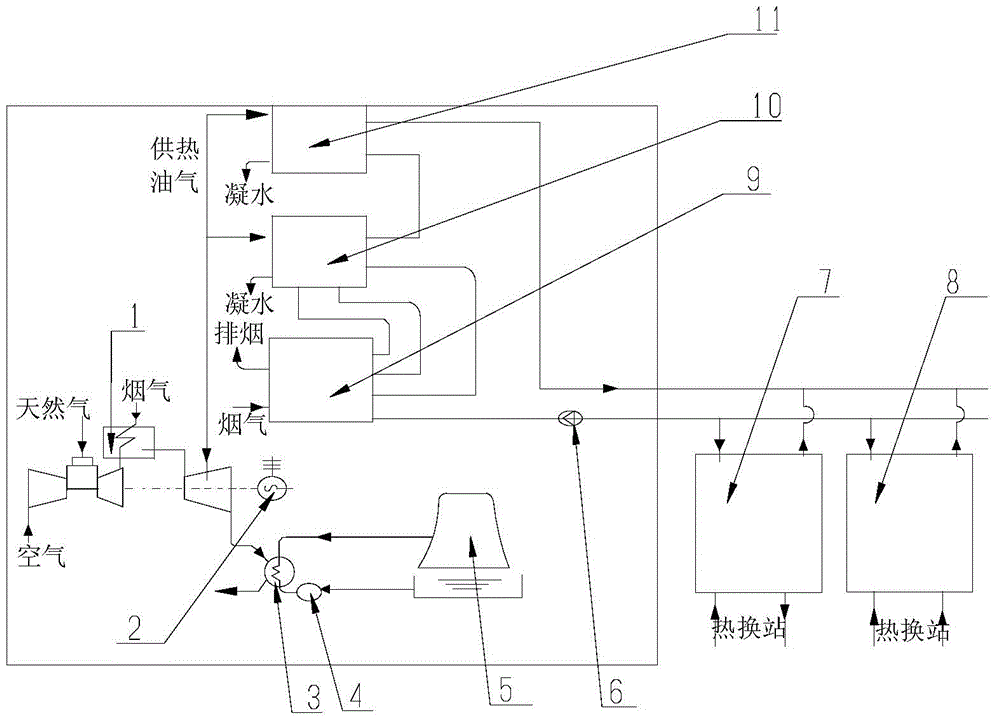
[0012] Please refer to the attached figure 1 , in an embodiment of the present invention, a gas-fired cogeneration heat supply system based on absorption heat exchange, including a waste heat boiler 1, a generator 2, a condenser 3, a cooling circulating water pump 4, a cooling tower 5, and a heat network circulating pump 6. The first absorption heat exchange unit 7, the second absorption heat exchange unit 8, the flue gas exchanger 9, the absorption heat pump ...


PUM


Abstract

The invention discloses a fuel gas combined heat and power generation heating supply system based on absorption-type heat exchange. The fuel gas combined heat and power generation heating supply system comprises a waste heat boiler, an electric generator, a condenser, a cooling circulation pump, a cooling tower, a heat supply network circulating pump, a first absorption-type heat exchange unit, a second absorption-type heat exchange unit, a smoke ventilation device, an absorption-type heat pump and a gas and water heat exchanger; a steam turbine is installed on one side of the waste heat boiler, and the steam turbine is connected with the electric generator; the condenser and the steam turbine are connected with pipelines of the cooling tower; the smoke ventilation device is connected with pipelines of the first absorption-type heat exchange unit and the second absorption-type heat exchange unit. According to the fuel gas combined heat and power generation heating supply system based on the absorption-type heat exchange, in a heating station, by means of an absorption-type heat exchange technology, a conventional plate heat exchanger is replaced with the absorption-type heat exchange units, actual supply water temperature of a heat supply network is 120 DEG C, the return water temperature of 25 DEG C of the heat supply network is achieved so as to recycle a large number of waste heat of power stations, and the energy utilization efficiency of the system is improved.

Description

technical field [0001] The invention relates to the technical field of application of heat exchange systems, in particular to a gas heat and power cogeneration heat supply system based on absorption heat exchange. Background technique [0002] The main component of natural gas is methane (CH4), with negligible sulfur content, and almost no SO2 and soot in combustion. At the same time, because the combustible components of natural gas contain a large amount of hydrogen, the CO2 contained in the combustion products will also be significantly reduced, only 60% of coke and 80% of petroleum. For some key cities, the requirements for energy conservation and emission reduction are relatively strict. Under the premise of investigating various power generation and heating technologies, gas cogeneration technology has become the first choice for major thermal power centers. The gas-fired cogeneration device has outstanding advantages such as high power generation efficiency, small fo...

Claims


Application Information

Patent Timeline
Patent Type & Authority Applications(China)
IPC IPC(8): F25B27/02F24D3/18F01K11/02F01D15/10
CPCY02A30/274Y02P80/15F24D3/18F01D15/10F01K11/02F24D2200/126F24D2200/16
Inventor 陈江华
Owner ZHONGNENG SHIHUA BEIJING ENERGY SAVING SCI & TECH
Learn More