
Device and method for testing glare of lens module

A lens module and testing equipment technology, applied in optics, testing optical performance, instruments, etc., can solve problems such as the inability to place mechanical parts and easy generation of glare, and achieve the effects of correcting design defects, reducing production costs, and improving efficiency

Inactive Publication Date: 2012-05-23
HONG FU JIN PRECISION IND (SHENZHEN) CO LTD +1
View PDF5 Cites 1 Cited by
  • Summary
  • Abstract
  • Description
  • Claims
  • Application Information

AI Technical Summary

Problems solved by technology

[0003] As the camera module develops towards thinner and shorter, the height of the camera module is compressed. Therefore, the number and size of the mechanism parts inside the camera module are also relatively compressed and reduced, making the mechanism originally used to block glare or eliminate glare Parts cannot be placed, making flare easily generated inside the lens

Method used


Image

  • Device and method for testing glare of lens module
  • Device and method for testing glare of lens module
  • Device and method for testing glare of lens module

Examples


Embodiment Construction

[0011] The present invention will be further described in detail below in conjunction with the accompanying drawings.

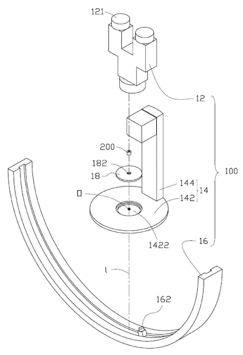
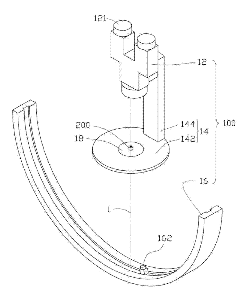
[0012] Please refer to Figure 1 to Figure 2 , is a schematic diagram of the glare detection device 100 and the lens module 200 to be detected according to an embodiment of the present invention.

[0013] The glare detection device 100 is used to detect the glare in the lens module 200, and the glare detection device 100 sequentially includes an optical amplification unit 12, a base 14 and an arc-shaped slide rail 16 along the direction of the optical axis l .

[0014] The base 14 includes a supporting platform 142 . The carrying platform 142 has a fixing rod 144 on it.

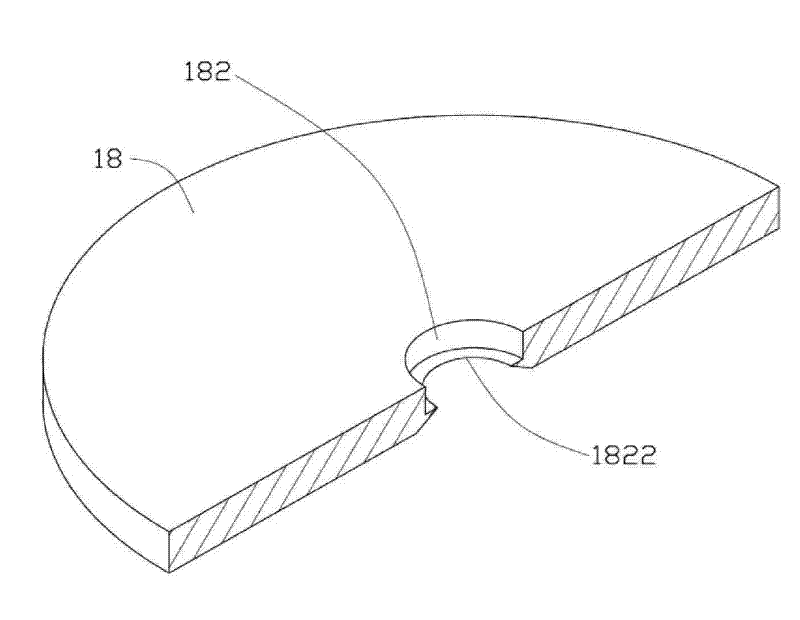
[0015] A center of the carrying platform 142 has a receiving through hole 1422 . The accommodating through hole 1422 is used for accommodating the lens module 200 to be inspected, or, the accommodating through hole 1422 can be used for accommodating a lens carrier 18 . The lens carrying...


PUM


Abstract

The invention provides a device for testing the glare of a lens module, which is used for testing glare condition in the lens module and comprises: a pedestal which comprises a bearing platform, wherein the bearing platform is provided with an accommodating through hole used for holding the lens module to be tested; an optical amplifying unit fixed above the pedestal, wherein the optical axis ofthe optical amplifying unit and the central line of the holding through hole are arranged on the same straight line, and the optical amplifying unit is used for observing the lens module; a circular arc-shaped slide rail arranged opposite to the pedestal, wherein the circle center of the circular arc-shaped slide rail coincides with the center of the holding through hole on the bearing platform; and a light source which is arranged on the circular arc-shaped slide rail and capable of sliding along the circular arc-shaped slide rail. The invention also provides a method for testing the glare of the lens module.

Description

technical field [0001] The invention relates to a glare detection device and a detection method, in particular to a lens module glare detection device and a detection method thereof. Background technique [0002] In recent years, with the development of optical products, the scope of application of lens modules continues to expand, such as digital cameras, mobile phones with camera functions and other electronic products. For electronic products, especially consumer electronic products, the development trend is light weight and thinner, and the corresponding lens modules installed therein are also becoming smaller and smaller, and the requirements for precision are also getting higher and higher. [0003] As the camera module develops towards thinner and shorter, the height of the camera module is compressed. Therefore, the number and size of the mechanism parts inside the camera module are also relatively compressed and reduced, making the mechanism originally used to block...

Claims


Application Information

Patent Timeline
Patent Type & Authority Patents(China)
IPC IPC(8): G03B43/00G01M11/02
Inventor 张耕铭
Owner HONG FU JIN PRECISION IND (SHENZHEN) CO LTD
Learn More