
Three methods for detecting operation state of motor in rotation resisting switch

A technology of running state and anti-rotation is applied in the field of detecting the running state of the motor in the three kinds of anti-rotating switches, which can solve the problems of motor damage, adverse production influence, and high working environment temperature, and achieves the effects of intuitive display, simple structure and low cost.

Inactive Publication Date: 2014-02-12
韩小东
View PDF6 Cites 1 Cited by
  • Summary
  • Abstract
  • Description
  • Claims
  • Application Information

AI Technical Summary

Problems solved by technology

[0004] Because the motor of the material level switch is in the running state for a long time, and the resistance rotary material level switch is usually used to detect the environment of pellets or powder, and it is in direct contact with the material, causing the working environment temperature of the motor to be relatively high, so the motor is often damaged , causing the material level switch to fail to work normally, or to output a false signal, which will adversely affect production
[0005] When the material level switch is damaged, the post workers often cannot find it immediately
Even a professional maintenance worker cannot correctly judge whether the material level switch is good or bad without removing it.

Method used


Image

  • Three methods for detecting operation state of motor in rotation resisting switch
  • Three methods for detecting operation state of motor in rotation resisting switch
  • Three methods for detecting operation state of motor in rotation resisting switch

Examples


Embodiment Construction

[0019] Below in conjunction with accompanying drawing, this design patent is described in further detail.

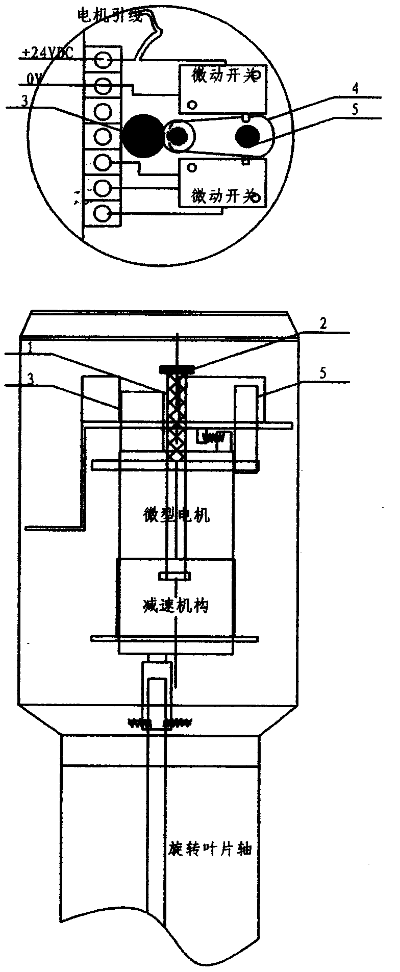
[0020] figure 1 . As shown, the driving mechanism of the rotary resistance type material level switch is composed of a micro motor and a reduction mechanism. The shaft of the micro motor is extended by about 30MM, slightly higher than the micro switch. See figure 1 The middle shaded part (1); and install a rotating indicator piece (2) at the end of the extended motor shaft. The extended shaft (1) of the micromotor needs to be explained when ordering the micromotor. Because the micro motor has a certain deflection margin in the controller, it is necessary to cut an irregular movable hole (4) on the panel of the controller to ensure the movement of the micro motor shaft (1) and the motor deflection shaft (5) . (3) is the fixing pin of micromotor and control panel.

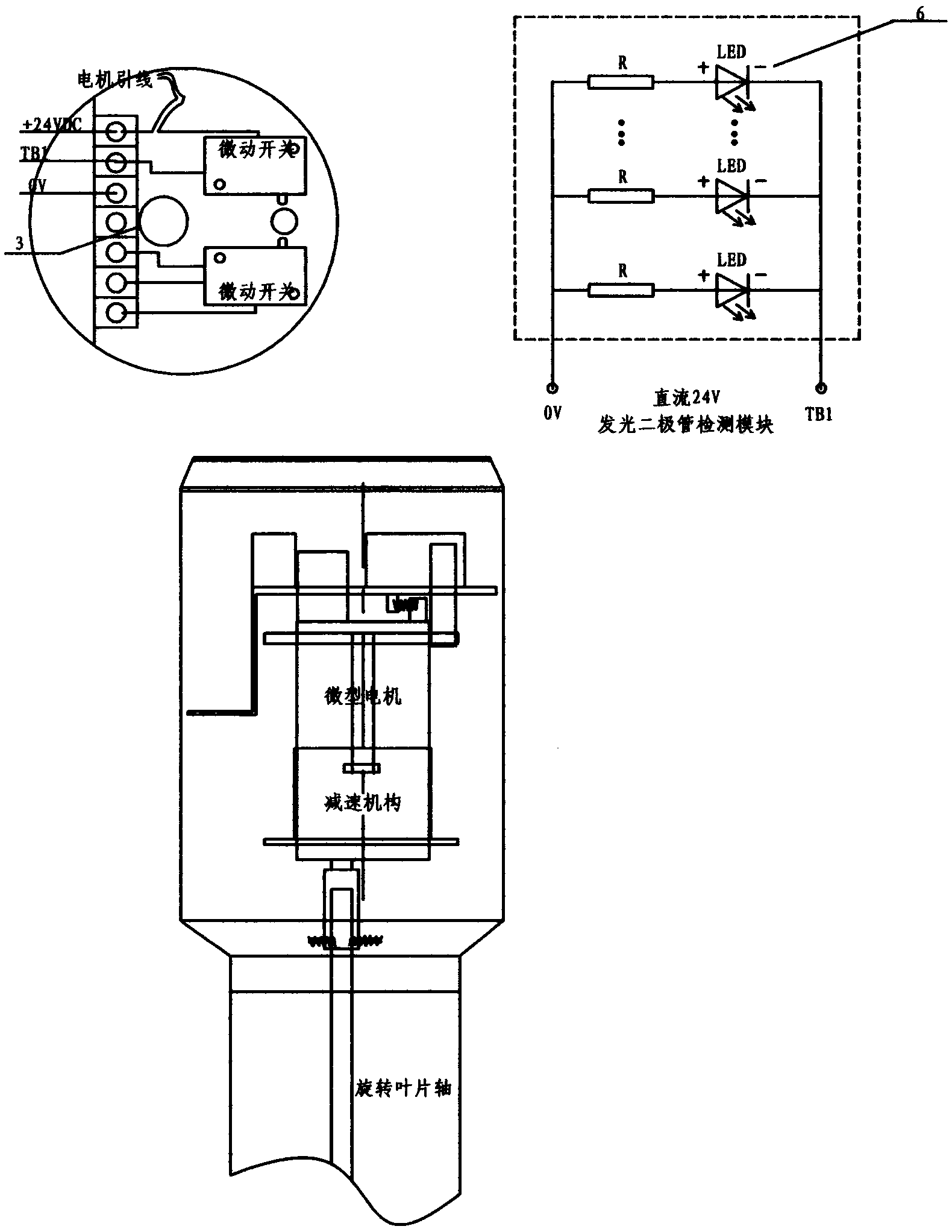
[0021] figure 2 As shown in ., the light emitting diode module (6) is only for the resistive rotary ...


PUM


Abstract

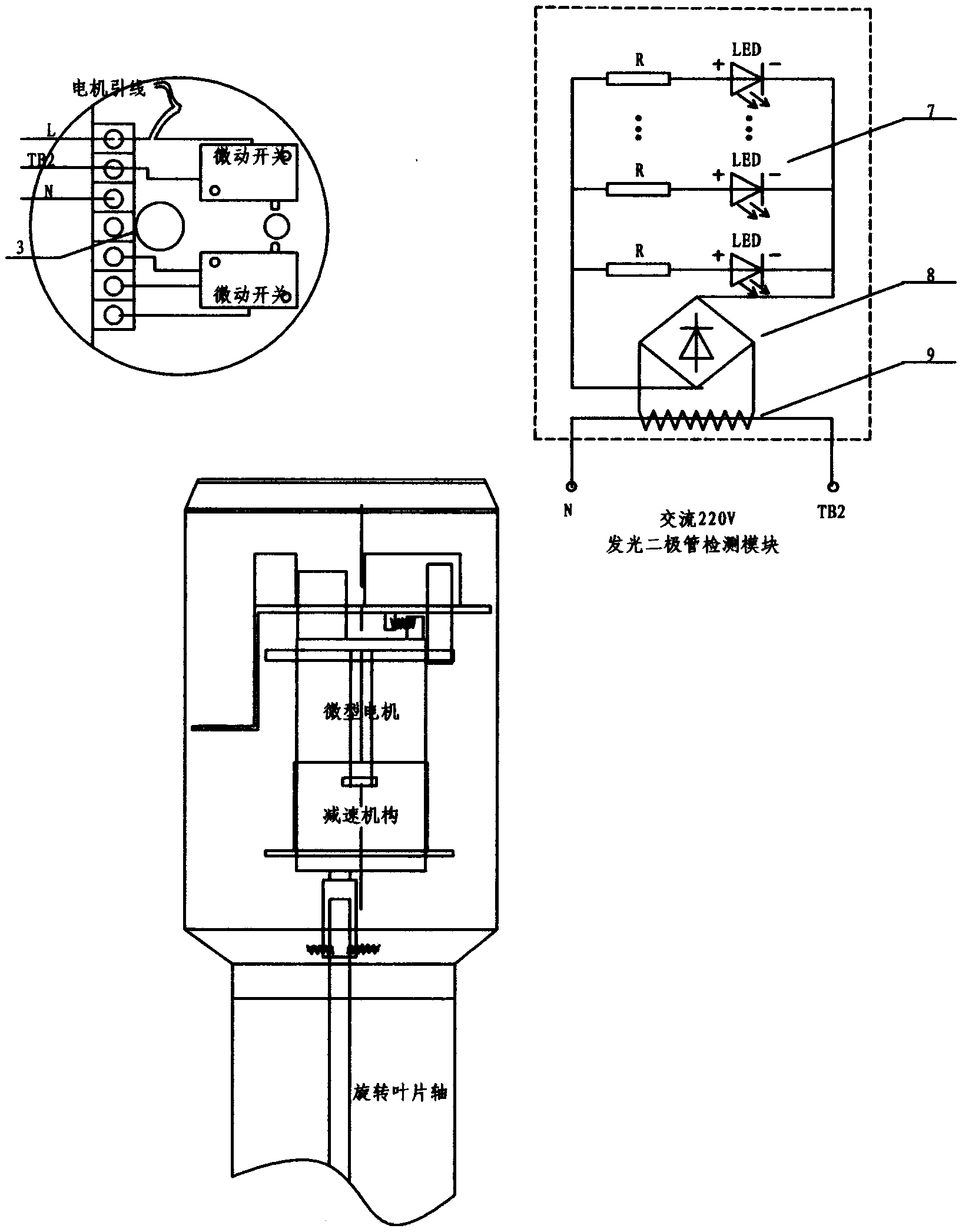
The invention discloses three methods for detecting the operation state of a motor in a rotation resisting switch. A pure mechanical structure is used in one method, the shaft of the micro motor is mainly lengthened, a rotation indicating sheet is added to the shaft end, and whether the micro motor operates normally or not is clearly judged through the rotation indicating sheet. A light-emitting diode module is added to another method and is only for the direct current supply rotation resisting switch, and whether the micro motor is good or not is judged through the lighting or extinguishing of a light-emitting diode. A module integrating a mutual inductor, a rectification function and the light-emitting diode is added to the third method and is for an alternating current supply rotation resisting switch, and whether the micro motor is good or not is judged through the lighting and extinguishing of the light-emitting diode. The methods have the advantages that the rotation resisting switch does not need to be pulled out, whether the micro motor in the rotation resisting switch works normally or not can be judged, and therefore whether the rotation resisting switch works normally or not is judged, and the maintenance and fault diagnosis of equipment are facilitated; the original rotation resisting switch can be properly transformed, investment is low, and the effect is significant.

Description

technical field [0001] This design patent involves three methods for detecting the running state of the motor in the rotary switch, which are divided into mechanical type and electronic type. The electronic type is suitable for the rotary type material level switch of AC and DC power supply modes. Background technique [0002] The anti-rotation material level switch usually connects the anti-rotation blade with the clutch through the transmission shaft. When the material is not in contact with the material, the motor keeps running normally; when the blade contacts the material and causes resistance, the motor will stop rotating, and the mechanism will output a contact signal at the same time. And measure the material level height. [0003] The anti-rotary material level switch is suitable for chemical plastics, pharmaceuticals, plastics, cement, chemical fertilizers, and food powder manufacturing and processing industries. [0004] Because the motor of the material level sw...

Claims


Application Information

Patent Timeline
Patent Type & Authority Applications(China)
IPC IPC(8): G01R31/34
Inventor 韩小东
Owner 韩小东
Learn More