Periphery surveillance device for vehicles

A monitoring device and vehicle technology, which is applied to vehicle components, optical observation devices, vehicle safety arrangements, etc., can solve the problem that the occupants are not easy to know, and achieve the effect of light computing load

Inactive Publication Date: 2010-01-20
AISIN SEIKI KK
View PDF1 Cites 7 Cited by
  • Summary
  • Abstract
  • Description
  • Claims
  • Application Information

AI Technical Summary

Problems solved by technology

That is, in the driving assistance device disclosed in Patent Document 1, it is not easy for the occupant to know which part is enlarged within the shooting range of the camera.

Method used


Image

  • Periphery surveillance device for vehicles
  • Periphery surveillance device for vehicles
  • Periphery surveillance device for vehicles

Examples


no. 1 approach

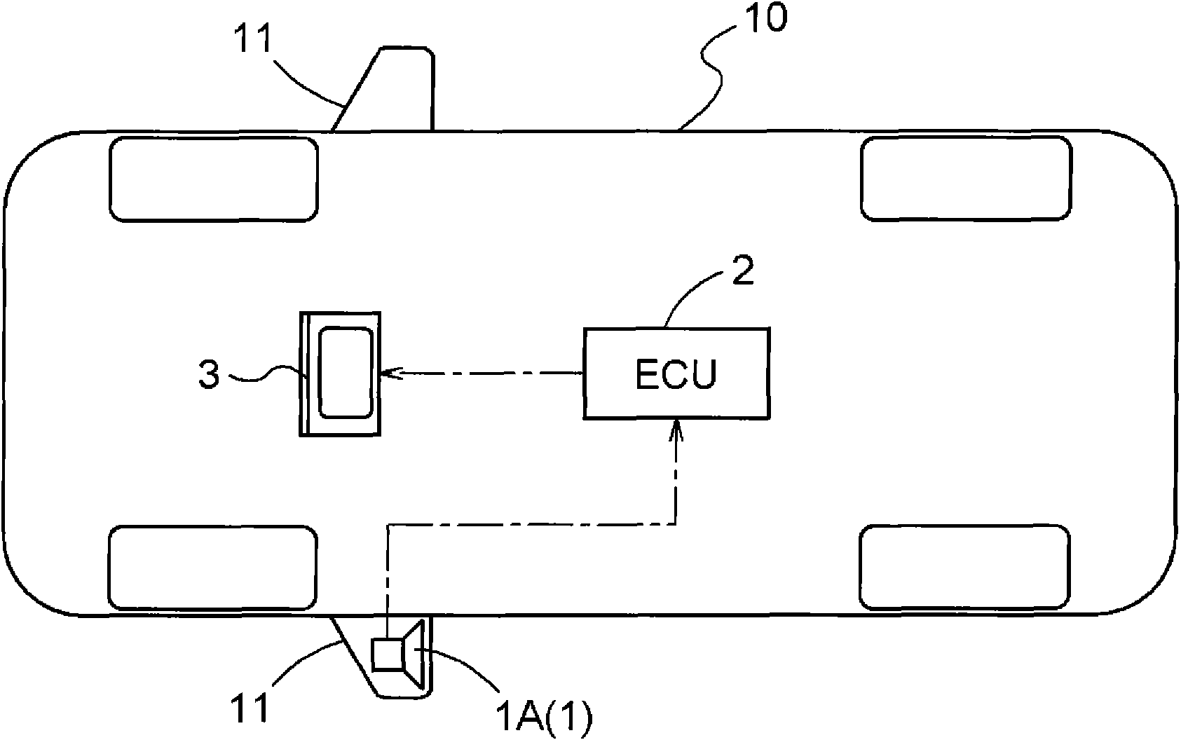
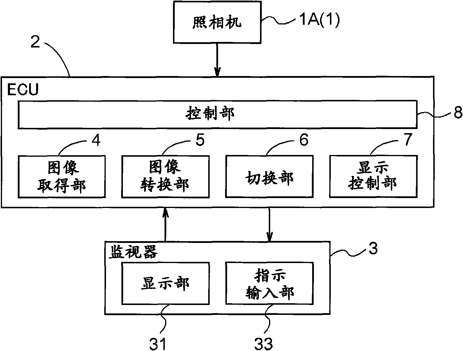
[0037] Hereinafter, an embodiment of the surrounding area monitoring device for a vehicle (hereinafter simply referred to simply as the surrounding area monitoring device) of the present invention will be described with reference to the drawings. figure 1 It is a block diagram schematically showing a configuration example of a vehicle 10 equipped with the surrounding area monitoring device of the present invention. figure 2 It is a block diagram schematically showing a configuration example of the vehicle periphery monitoring device of the present invention.

[0038] The peripheral monitoring device of the present invention is constructed with the ECU 2 as the core. The ECU 2 has a microprocessor and a DSP (digital signal processor) that process input information (for example, image information). The ECU 2 is composed of circuits with the processor as a core component. In addition, the ECU 2 has a storage unit composed of a memory, a register, or the like built in the proc...

no. 2 approach

[0061] In the above-mentioned example, the case where an image based on the wide-area imaging data captured by one camera 1 ( 1A) mounted on the vehicle 10 is displayed on the monitor 3 has been described as an example. However, the camera 1 is not limited to one, and the present invention can also be applied to a case where an image based on wide-area imaging data captured by a plurality of cameras 1 is displayed on the monitor 3 . Next, use Figure 12 to Figure 17 , to describe the second embodiment of the present invention. Figure 12 It is a block diagram schematically showing another configuration example of the vehicle 10 equipped with the surrounding area monitoring device of the present invention. Figure 13 It is a block diagram schematically showing another configuration example of the surrounding area monitoring device of the present invention.

[0062] In the present embodiment, two cameras 1 are provided as imaging devices for imaging surrounding scenes of the v...


PUM


Abstract

Wide-area imaging data obtained by imaging the scene around a vehicle can be converted into either wide-area display data for displaying the scene in the same field of view on a display or zoom-in display data for zooming in a part of the image representing by the wide-area imaging data. When the image on the screen of the display is changed from one of the wide-area display and the zoom-in display to the other, the target region corresponding to the display data after the change on the image represented by the display data (V1) before the change is determined as a highlighted region (E) on the screen and highlighted. Until the area of the highlighted region (E) becomes equal to that of the target region represented by the display data after the change, the area of the highlighted region (E) varies. Finally, the image represented by the display data after the change is displayed in the highlighted region (E).

Description

technical field [0001] The present invention relates to a peripheral monitoring device for a vehicle, which displays the scene around the vehicle on a display device in the vehicle based on image data acquired by an imaging device mounted on the vehicle. Background technique [0002] In recent years, people's awareness of safety while driving a vehicle has increased, and various techniques for improving safety by assisting the driver's driving operations and the like have been considered and put into practice. For example, driving assistance devices that use a camera mounted on a vehicle to take pictures of places that are difficult for occupants to see and display them on a monitor device inside the vehicle have been put into practical use. Japanese Patent Laid-Open No. 2004-194071 as Patent Document 1 discloses a driving assistance device that displays image data acquired by cameras mounted on side mirrors of a vehicle on a monitor device in a vehicle interior. [0003] T...

Claims


Application Information

Patent Timeline
Patent Type & Authority Applications(China)
IPC IPC(8): H04N7/18B60R1/00G06T1/00B60R21/00
CPCB60R2300/70B60R1/00B60R2300/102B60R2300/8026G06T3/0018H04N7/181H04N7/18
Inventor 久保山刚渡边一矢山中隆司
Owner AISIN SEIKI KK
Why Eureka
Try Eureka