Welding method of solder ball welding device

A technology of a welding device and a welding method, which is applied to the welding of solder ball welding devices and the laser welding field of laser welding devices, can solve the problems of inability to identify processing points coaxially with high precision, inability to continuously replenish solder balls, and inability to select nozzles, etc. Achieve the effect of solving solder ball welding process problems, quick solder point judgment effect, and easy infiltration and spreading.

Active Publication Date: 2020-04-17
WUHAN BESKYS TECH CO LTD
View PDF15 Cites 6 Cited by
  • Summary
  • Abstract
  • Description
  • Claims
  • Application Information

AI Technical Summary

Problems solved by technology

Its shortcoming is that this method only uses laser melting pre-arranged solder balls to complete the soldering, and cannot continuously replenish solder balls during the soldering process, that is, the soldering process is decomposed into two stages: ball placement and soldering, and the patent cannot be based on Nozzles with different apertures are selected for the size of the pad, and there is no coaxial vision, so the position of the processing point cannot be recognized coaxially with high precision
Its shortcomings are: the first patent is mainly used for single solder ball welding, the second patent controls the start and stop of the laser through the change of inner cavity air pressure, and the above two patents cannot continuously replenish solder balls under continuous laser irradiation

Method used


Image

  • Welding method of solder ball welding device
  • Welding method of solder ball welding device
  • Welding method of solder ball welding device

Examples


Embodiment 1

[0065] refer to Figure 4 , is a flow chart of the solder ball soldering process for solder pads with a pad size less than or equal to 3.04mm. When soldering such pads, it is necessary to ensure that the solder balls are accurately melted at the specified position. The solder ball welding method based on this device includes four stages: visual positioning, laser preheating, solder ball implantation, and solder joint formation. specific:

[0066] ⑴Visual positioning stage, image channel, detect the position of the product to be welded and perform correction.

[0067] ⑵In the laser preheating stage, the laser channel blows protective gas into the transition chamber, and the light is directly irradiated on the pad and kept, so that the pad is fully preheated.

[0068] (3) In the solder ball implantation stage, the laser channel implants single or multiple solder balls, and the solder balls melt quickly and drop on the pad.

[0069] ⑷In the solder joint forming stage, the lase...

Embodiment 2

[0071] refer to Figure 5, is a flow chart of the solder ball welding process for pads larger than 3.04mm in size. When soldering this pad, it is only necessary to ensure that the solder balls melt within a certain area. The process includes: visual positioning, laser preheating, solder ball planting There are four stages of entry and solder joint formation.

[0072] ⑴Visual positioning stage, image channel, detect the position of the product to be welded and perform correction.

[0073] ⑵In the laser preheating stage, the laser channel blows protective gas into the transition chamber, and the light is directly irradiated on the pad and kept, so that the pad is fully preheated.

[0074] (3) In the solder ball implantation stage, the laser channel implants single or multiple solder balls, and the solder balls melt quickly and drop on the pad.

[0075] ⑷ Solder joint forming stage, image channel, adjust the focusing mirror, increase the pad spot and keep the laser irradiation ...


PUM


Abstract

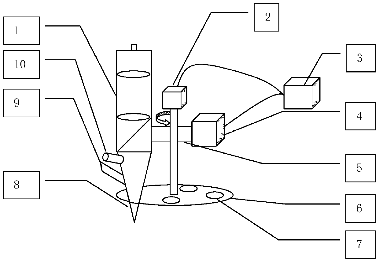
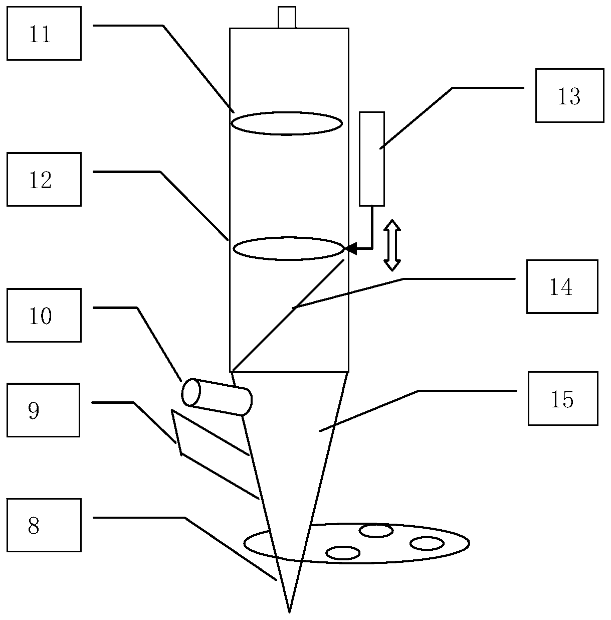
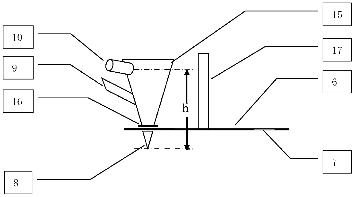
The invention designs a welding method of a solder ball welding device. According to the solder ball welding method, a solder ball welding device with a coaxial vision system is adopted, a laser focusing head, a controller, a CCD camera and a rotating disc are arranged in the solder ball welding device, part of a laser light path coincides with a vision imaging light path, and coaxial and same-focus laser and vision are achieved. During welding, welding nozzles of different sizes can be switched by rotation, rapid switching between solder ball welding of different sizes and visual imaging is achieved, the sizes of light spots are rapidly adjusted to adapt to the nozzles of different hole diameters, and the requirements of welding spots of multiple specifications are met. Through the processes of preheating before welding, continuous ball spraying and light supplementing after welding, sound welding of welding spots with different sizes and high heat dissipation speed are achieved. During welding, random solder balls can be supplemented in real time, and after entering the transition bin, the solder balls are directly melted in the falling process and then drop on a bonding pad without staying at a nozzle opening, so that the welding time is shortened, and the production efficiency is improved.

Description

technical field [0001] The invention relates to a welding method of a solder ball welding device, in particular to a laser welding method of a laser welding device using tin balls as solder, and belongs to the technical field of laser solder ball welding. Background technique [0002] Laser solder ball welding is mainly used in small and fine processing occasions such as hard disk heads, camera modules, and VCM enamelled coil modules. Traditional solder ball welding has the advantages of no spatter residue, no laser burns, and good tin quantity consistency. Existing content such as the Chinese utility model patent "Automatic Solder Ball Soldering Machine" (201821024456.1) or the invention patent "A Solder Ball Welding Structure and Method for Precise and Fine Welding Areas" (201710985532.9) is that the laser does not directly When the solder ball is irradiated on the solder point, the solder ball is melted and then transported to the product to be soldered by the solder ball...

Claims


Application Information

Patent Timeline
Patent Type & Authority Applications(China)
IPC IPC(8): B23K1/005B23K3/06B23K3/08
CPCB23K1/0056B23K3/0623B23K3/08B23K3/087
Inventor 王浩徐琦邱浩波蔡仁树叶凯
Owner WUHAN BESKYS TECH CO LTD
Why Eureka
Try Eureka