
Liquid supply device and liquid ejecting apparatus

A liquid supply and liquid technology, applied in printing and other directions, can solve problems such as leakage and pollution inside the printer device

Active Publication Date: 2010-01-27
SEIKO EPSON CORP
View PDF1 Cites 4 Cited by
  • Summary
  • Abstract
  • Description
  • Claims
  • Application Information

AI Technical Summary

Problems solved by technology

Therefore, due to tolerances in the formation of each structural member, etc., a gap may occur in the sealing portion such as the pump chamber formed between the facing surfaces of the structural members fixed in a stacked state, and leakage to the outside of the pump chamber may occur from such a gap. Ink may leak to the outside of the ink supply device composed of a laminated structure
And, when the ink leaks from the ink supply device, due to the ink, the problem of contaminating the inside of the printer occurs.

Method used


Image

  • Liquid supply device and liquid ejecting apparatus
  • Liquid supply device and liquid ejecting apparatus
  • Liquid supply device and liquid ejecting apparatus

Examples


Embodiment Construction

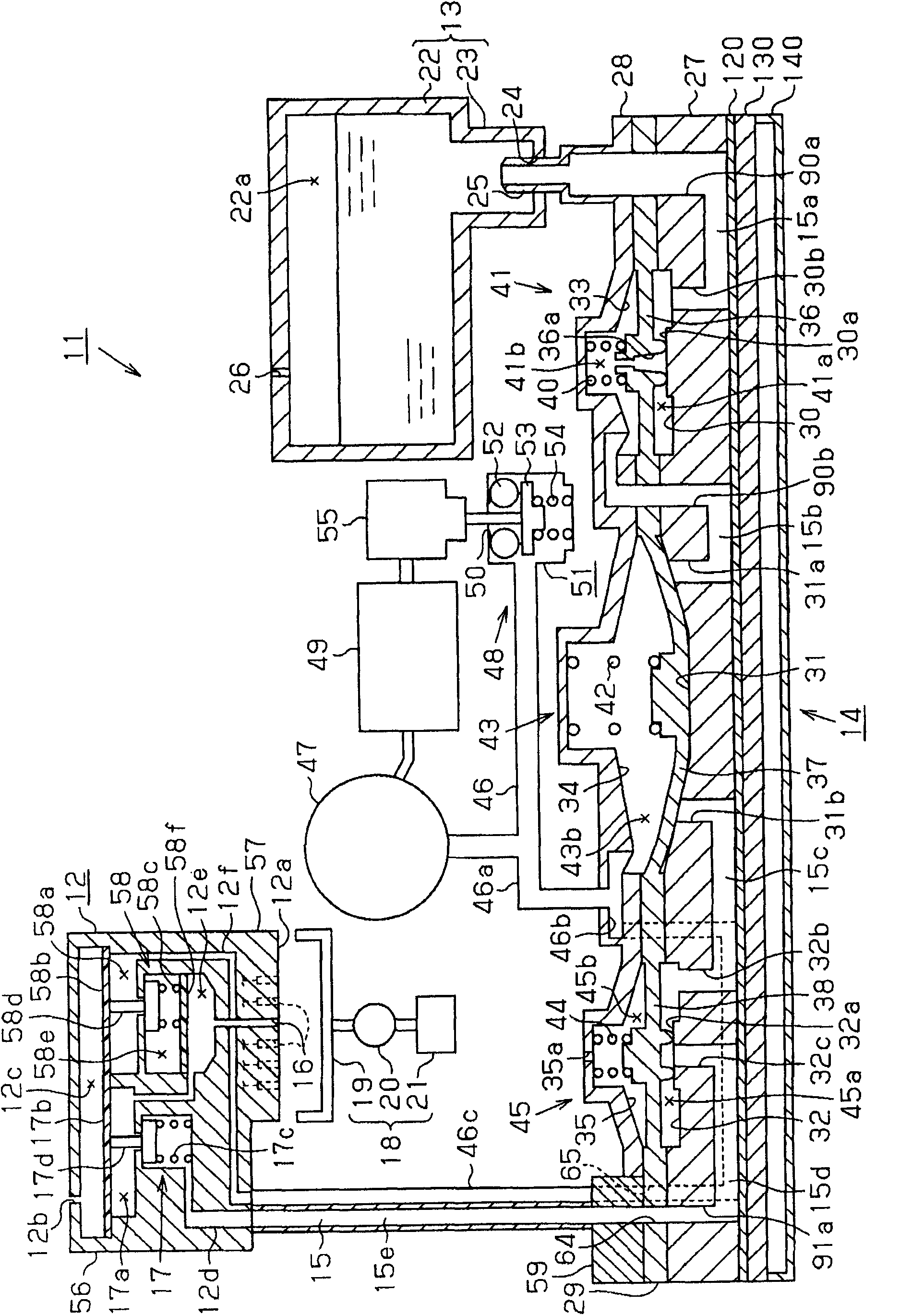
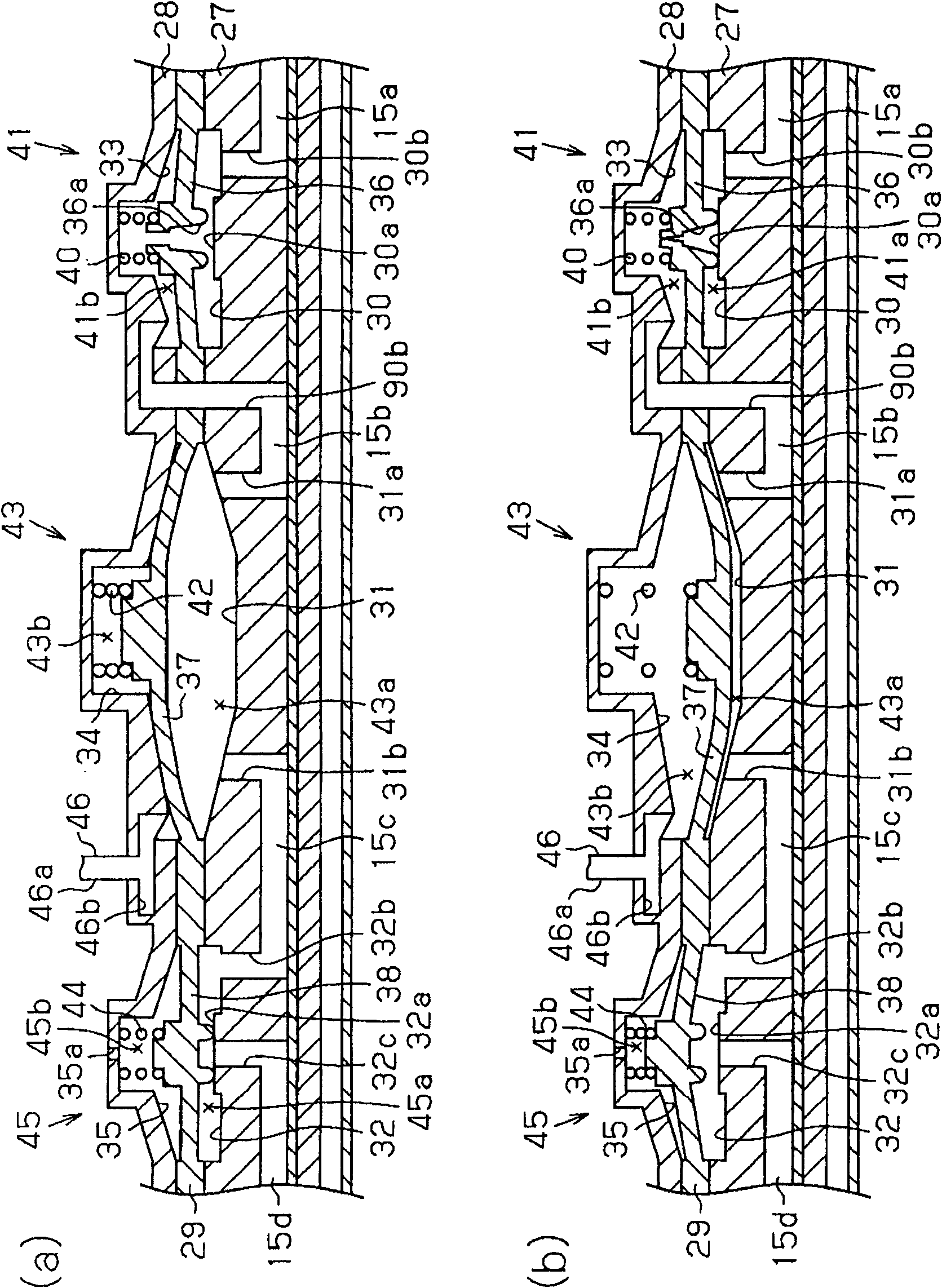
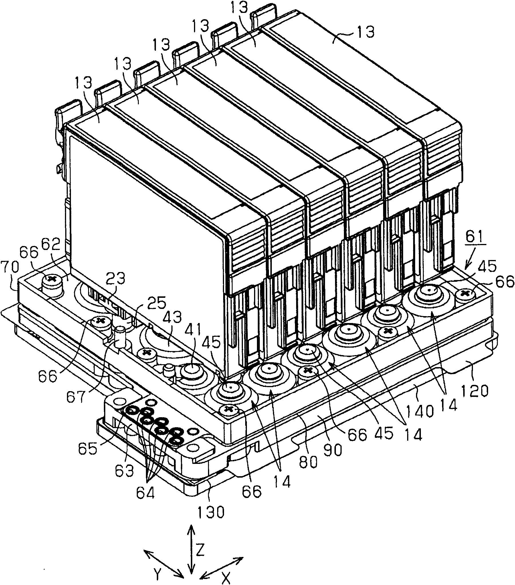
[0048] Below, use Figure 1 to Figure 20 , and an embodiment in which the present invention is embodied as an inkjet printer (hereinafter referred to as "printer") which is one type of liquid ejecting apparatus will be described.

[0049] Such as figure 1 As shown, the printer 11 of this embodiment includes: a recording head unit 12 as a liquid ejection mechanism for ejecting ink (liquid) to a target (for example, a recording medium such as paper) (not shown); An ink supply device 14 supplies ink contained in an ink cartridge 13 serving as a liquid supply source. In the ink supply device 14, a part of the ink flow path 15 is provided. The upstream end of the ink flow path 15 is connected to the ink cartridge 13 and the downstream end is connected to the recording head unit 12. Ink is supplied from the upstream side of the side to the downstream side of the recording head unit 12 side.

[0050] The printer 11 of this embodiment is an inkjet type serial printer or a line prin...


PUM


Abstract

The invention provides a liquid supply device capable of suppressing an influence caused due to liquid leakage and a liquid ejecting apparatus including the liquid supply device. An ink supply device of a printer comprises: an ink supply passage for supplying the ink from an ink box to a recording head and a pump. The ink supply device comprises a passage forming member which has a certain shape in which the liquid supply passage is formed; and a flexible diaphragm forming member (80) which is provided with a diaphragm which forms a part of a wall surface of the pump chamber and is displaceable to increase or decrease the volume of the pump chamber, wherein a lamination structure is formed by laminating the diaphragm forming member and the passage forming member so as to form the pump chamber between the facing surfaces thereof, and the outer circumference of the diaphragm forming member is provided with an outer circumference sealing portion which prevents the liquid, which has leaked from the liquid supply passage to a space between the facing surfaces of the diaphragm forming member and the passage forming member, from flowing outside the lamination structure.

Description

technical field [0001] The present invention relates to a liquid supply device and a liquid ejection device. Background technique [0002] Conventionally, an inkjet printer (hereinafter, referred to as a "printer") is known as a liquid ejecting device that ejects a liquid onto a target. In this printer, ink (liquid) supplied to a recording head (liquid ejection mechanism) is ejected from nozzles formed on the recording head to perform printing on a recording medium as a target. In addition, in such a printer, recently, for example, as described in Patent Document 1, it has been proposed that an ink flow path (liquid supply flow path) connecting the ink tank (liquid supply source) and the recording head is equipped with a A pump that pressurizes and supplies ink from the ink cartridge side to the recording head side to drive the pump. [0003] In the printer of this patent document 1, a laminated structure is constituted by laminating a shape-fixed ink flow path forming mem...

Claims


Application Information

Patent Timeline
Patent Type & Authority Applications(China)
IPC IPC(8): B41J2/175B41J2/14B41J2/01
CPCB41J2/175B41J2/17553B41J2/1752B41J2/17596
Inventor 横内秀弥
Owner SEIKO EPSON CORP
Learn More