
Feeding device and recording device

A technology of conveying device and recording medium, which is applied in the directions of transportation and packaging, separation of objects, separation of piles, etc., and can solve problems such as formation of gaps

Inactive Publication Date: 2010-02-03
SEIKO EPSON CORP
View PDF1 Cites 4 Cited by
  • Summary
  • Abstract
  • Description
  • Claims
  • Application Information

AI Technical Summary

Problems solved by technology

Furthermore, if the abutment angle between the paper and the inclined surface changes in this way, the gap cannot be formed with high precision, and there is a risk of causing overlapping feeding of the paper.

Method used


Image

  • Feeding device and recording device
  • Feeding device and recording device
  • Feeding device and recording device

Examples


no. 1 approach

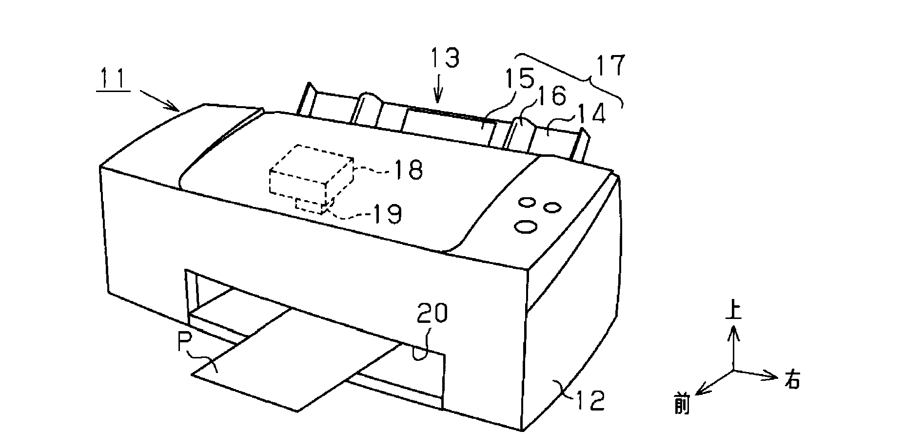
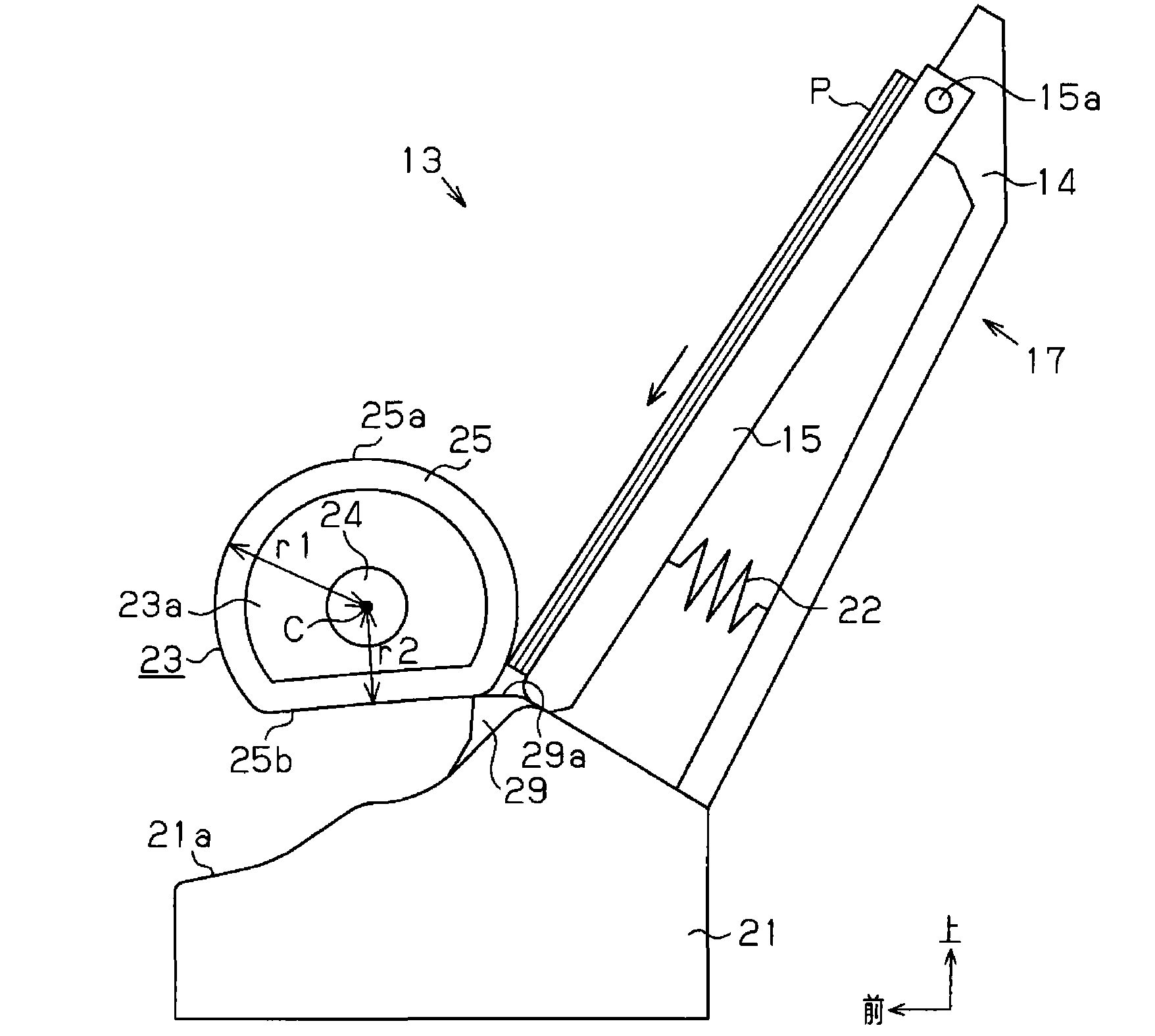
[0030] Below, use Figure 1 to Figure 5 An embodiment in which the recording device including the transport device according to the invention of the present application is embodied as an inkjet printer (hereinafter referred to as "printer") will be described. In addition, in the following description, when referring to "front-rear direction", "left-right direction", and "up-and-down direction", it means the direction based on the direction shown by the arrow in each figure.

[0031] Such as figure 1 As shown, in the printer 11 of this embodiment, an automatic paper feeder 13 serving as a conveying device for feeding paper P as a recording medium is equipped on the rear side of the main body 12 . A paper guide 17 serving as a loading unit is attached to the automatic paper feeder 13 . The paper guide 17 has a paper feed tray 14 , a hopper 15 , and an edge guide 16 . Also, the automatic paper feeder 13 has a paper feed drive mechanism (not shown) that feeds the paper P placed ...

no. 2 approach

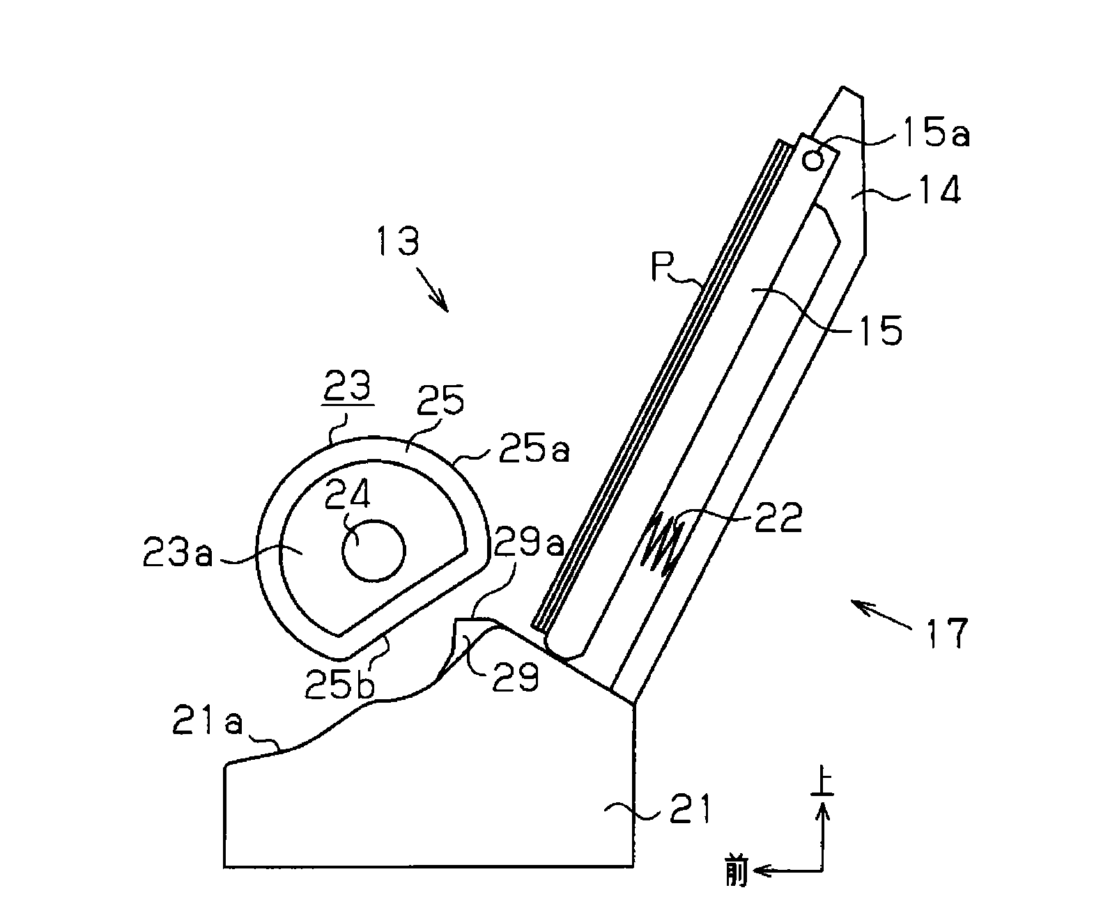
[0052] Below, according to Figure 6 A second embodiment in which the liquid ejecting apparatus of the present invention is embodied as a serial type inkjet printer will be described.

[0053] This embodiment is the same as the first embodiment in that in the automatic paper feeder 13 included in the printer 11 as a recording device, the paper feed roller 23 and the separation member 29 cooperate to separate the paper P. However, The guide roller 23 of this embodiment differs from 1st Embodiment in the point which has the spring member which biases the contact surface forming member 25 via a slider.

[0054] Hereinafter, the description will focus on points different from the first embodiment.

[0055] Such as Figure 6 As shown, in the inside of the base portion 23a of the paper feed roller 23, a storage hole is formed between the rotating shaft 24 and the abutment surface forming member 25 and at the part that abuts the separation member 29 when the paper P is separated. ...


PUM


Abstract

The present invention provides a feeding device capable of preventing a recording medium from being fed in overlapping with high precision, and a recording device having the feeding device. An automatically feeding device (13) contained in a printer includes: a sheet guiding member (17); a paper feeding roller (23) having a circumference surface (25a); a fixedly arranged separating component (29)having a tilted surface (29a); the circumference surface (25a) is formed from an elastic deformation abutting surface forming component (25). The paper feeding roller (23) is abutted on the topmost paper (P) of the paper (P) loaded in the sheet guiding member (17) by the circumference surface (25a), thereby the paper is output toward the feeding direction. One side of the topmost paper output by the paper feeding roller presses the circumference surface (25a) to make the abutting surface forming component generate elastic deformation, wherein the front end of the topmost paper collides with the tilted surface (29a), and to overcome the elastic recovering force of the abutting surface forming component to form a slot between the circumference surface and the separating component, the slot can only allow a piece of paper to pass through and be output.

Description

technical field [0001] The present invention relates to a conveying device such as a paper feeding device and a recording device such as an inkjet printer having the conveying device. Background technique [0002] Conventionally, in recording devices such as printers, in order to continuously record on a plurality of sheets of paper (recording media), there is a recording device having a paper feeding device (conveying device) that places sheets of paper in a stacked state. (That is, stacked) a plurality of paper sheets are separated one by one and automatically conveyed to the recording unit (for example, Patent Document 1). [0003] The paper feeding device of Patent Document 1 has: a paper cassette (loading unit) capable of stacking a plurality of sheets; sheets are output in a conveying direction; and a gate member for preventing sheets of a lower layer from being overlapped and conveyed in a conveying direction together with an uppermost sheet. [0004] Specifically, ...

Claims


Application Information

Patent Timeline
Patent Type & Authority Applications(China)
IPC IPC(8): B65H3/02B65H3/06B65H3/46B65H1/00
CPCB65H2801/06B65H3/0661B65H3/52B65H2404/1112B65H2404/1122B65H2402/46
Inventor 小林聪
Owner SEIKO EPSON CORP
Learn More