
Voice digital lock for safe

A safe and digital lock technology, applied in the field of anti-theft locks and locks, can solve the problems of easy loss or imitation of keys, low anti-theft performance, password theft by users, etc., to achieve the effect of simple and convenient use, improving confidentiality, and ensuring home security.

Inactive Publication Date: 2010-02-03
佛山市顺德区盈通实业有限公司
View PDF4 Cites 14 Cited by
  • Summary
  • Abstract
  • Description
  • Claims
  • Application Information

AI Technical Summary

Problems solved by technology

[0002] At present, there are two types of lock structures for safes: mechanical locks and electronic locks. The way to unlock a mechanical lock is to insert a key that matches the lock cylinder, or turn the dial according to the correct password to make the blade password slot, and turn the lock cylinder to pull the lock bolt to open the box. The door, but because the key is easy to lose or imitate, so its anti-theft performance is low; the electronic lock unlocks the signal by inputting the correct password, the control circuit controls the action of the electronic lock actuator, and the electromagnetic iron pulls in (or the motor rotates to drive the screw to move) ) to move the slide bar back, release the restraint of the driving mechanism in the mechanical lock, turn the handle of the mechanical lock, and make the driving mechanism matched with the cabinet door frame drive the lock tongue to move, open the cabinet door, and then the control circuit controls the electronic lock actuator to reset , send the handle away, and the slide bar will automatically return to the initial position under the action of the return spring. On the contrary, if the electronic lock password is entered incorrectly, the electronic lock actuator will not move, and the operator will not be able to open the cabinet door. The disadvantage is that the use of As an anti-theft means, electronic passwords will inevitably have password protection problems, and users are likely to be stolen by thieves unknowingly.

Method used


Image

  • Voice digital lock for safe
  • Voice digital lock for safe
  • Voice digital lock for safe

Examples


Embodiment Construction

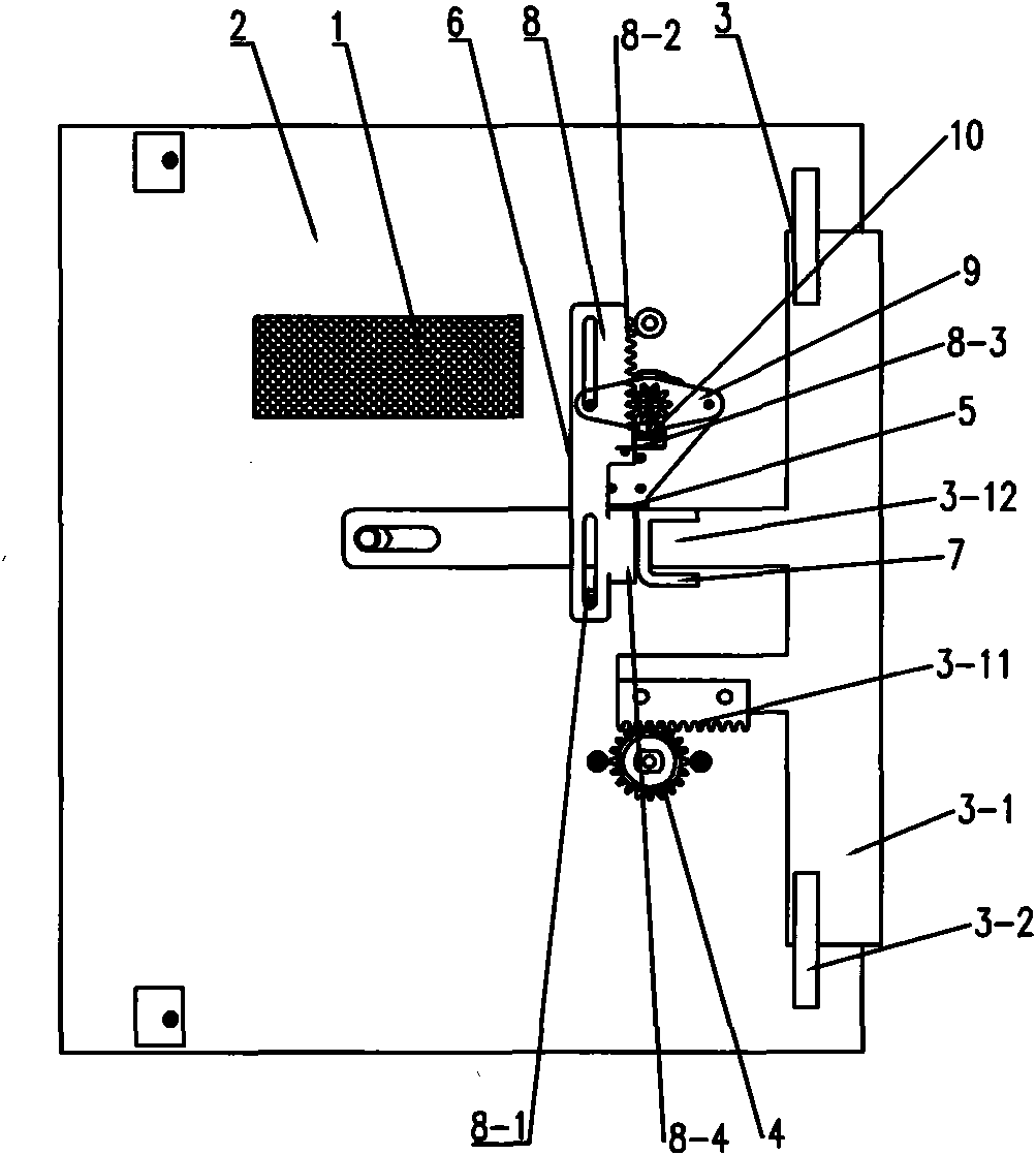
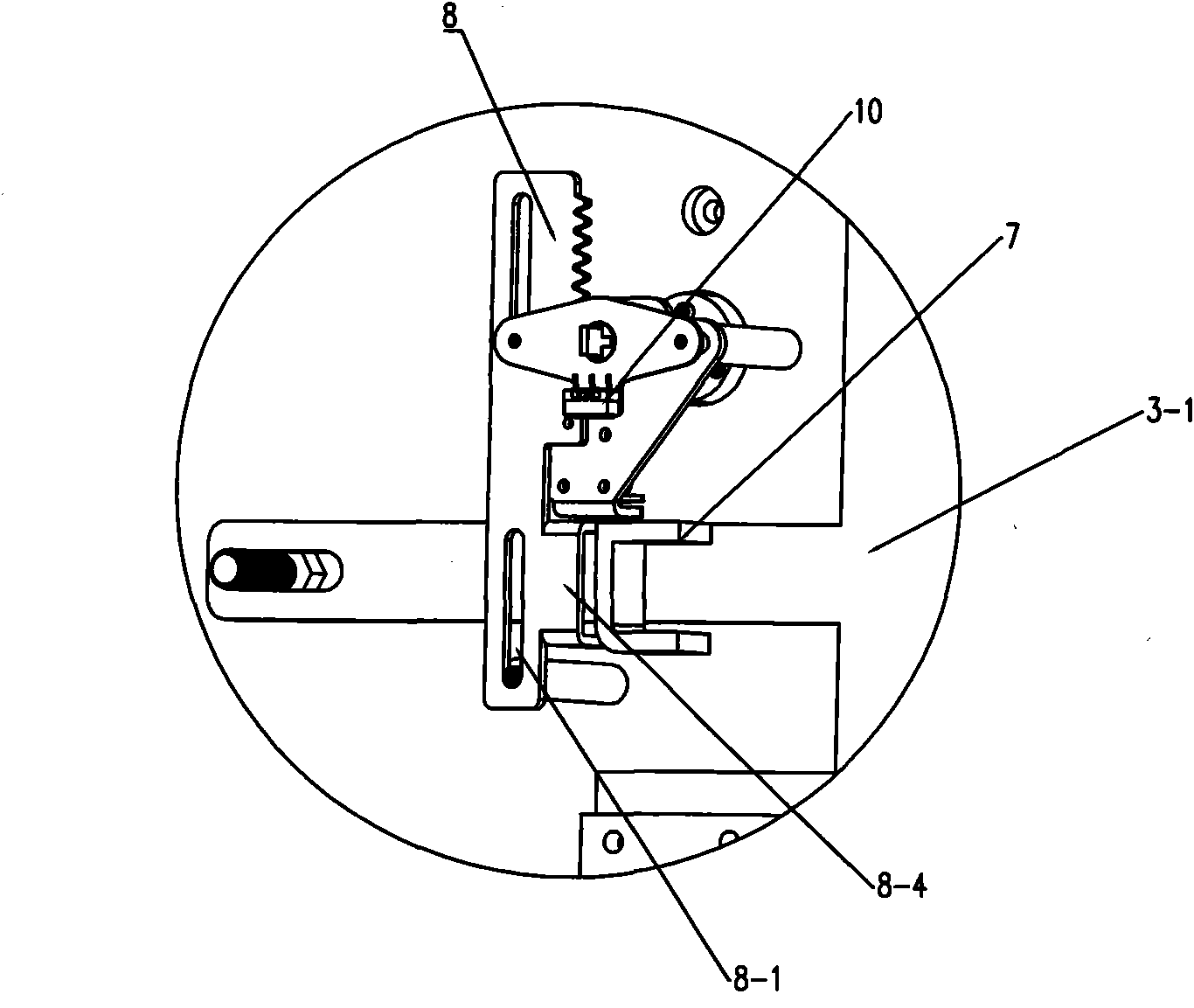
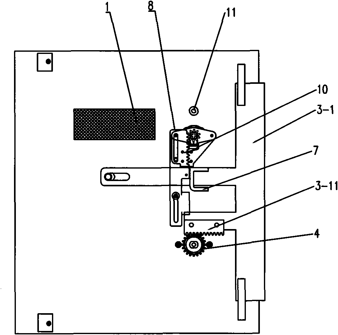
[0029] Such as Figure 1 to Figure 8 As shown, a voice digital lock for a safe of the present invention includes an electronic control device 1, a latch mechanism 3 installed on the safe door panel 2, a latch drive mechanism 4, and a lock mainly composed of an electromagnet 5 and its peripheral components. The stop mechanism 6 and the electromagnet 5 are electrically connected to the electronic control device 1, and the electromagnet 5 is generally a double-holding electromagnet. In this embodiment, the locking mechanism 3 includes a locking tongue 3-1, a guide mechanism 3-2, the locking bolt driving mechanism 4 is composed of a knob and a transmission gear, and the rear end of the locking tongue 3-1 is provided with teeth that mesh with the transmission gear. Bar 3-11 and the slide bar 3-12 matched with the guide mechanism 3-2, the surface of the slide bar 3-12 is provided with a locking block 7, and the mandrel of the electromagnet 5 leans against the back of the locking blo...


PUM


Abstract

The invention discloses a voice digital lock for a safe, comprising an electronic control device, a lock bolt mechanism arranged on the door panel of the safe, a lock bolt driving mechanism and a lockbolt stop mechanism mainly composed of an electromagnet and peripheral component thereof; wherein the electromagnet is electrically connected with the electronic control device. The voice digital lock is characterized in that the lock bolt stop mechanism also comprises a lock plate with teeth which is movably arranged at the periphery of the lock bolt mechanism, the lock plate with teeth is connected with a mechanic lock control device which drives the lock plate to do reciprocating movement, wherein the mechanic lock control device is mainly composed of a lock head and a key embedded with anID chip; the electronic device is internally provided with a detection circuit capable of identifying ID code key, and the periphery of the lock plate with teeth is provided with a micro switch capable of triggering the electromagnet to act. The invention combines key lock bead mechanical password, key chip password and user password into tripe password protection, so that opening rate of key isalmost reduced to zero; and the structure is simple and cost is low.

Description

technical field [0001] The invention relates to the technical field of anti-theft locks, in particular to a lock used on a safe. Background technique [0002] At present, there are two types of lock structures for safes: mechanical locks and electronic locks. The way to unlock a mechanical lock is to insert a key that matches its lock cylinder, or turn the dial according to the correct password to make the blade password groove, and turn the lock cylinder to pull the lock bolt to open the box. The door, but because the key is easy to lose or imitate, so its anti-theft performance is low; the electronic lock unlocks the signal by inputting the correct password, the control circuit controls the action of the electronic lock actuator, and the electromagnetic iron pulls in (or the motor rotates to drive the screw to move) ) to move the slide bar back, release the restraint of the drive mechanism in the mechanical lock, turn the handle of the mechanical lock, and make the drive m...

Claims


Application Information

Patent Timeline
Patent Type & Authority Applications(China)
IPC IPC(8): E05G1/026E05B37/20E05B49/00E05B47/06E05B45/06E05B19/00
Inventor 麦鹤远
Owner 佛山市顺德区盈通实业有限公司
Learn More