Lock core on-off structure with racing lock core

A technology of lock cylinder and front lock cylinder, which is applied to locks with rotating keys, construction locks, cylinder pin locks, etc., which can solve the problems of anti-theft performance impact and increased lock mutual opening rate, so as to reduce the mutual opening rate, Effect of improving safety and reducing possibility

Inactive Publication Date: 2008-08-27
雷先鸣
View PDF1 Cites 1 Cited by
  • Summary
  • Abstract
  • Description
  • Claims
  • Application Information

AI Technical Summary

Problems solved by technology

This lock cylinder clutch structure has some shortcomings in practical applications. The main problem is that there is only one contact part between the sliding block 1' and the locking side column 3'. , such as the front-end teeth of the key match the pins (although other teeth do not match), the corresponding end of the locking side column 3' will move radially inward along the lock cylinder, and under the action of the lock pin return spring, the lock pin 14 ' and the sliding block 1' will move inward along the axial direction of the lock cylinder for a short distance, and at this time, a small part of the lock pin 14' will extend into the front lock cylinder 6', connecting the front and rear lock cylinders 6' and 12' Integrate to realize unlocking, so that the mutual opening rate of the lock is increased, and the anti-theft performance is affected

Method used


Image

  • Lock core on-off structure with racing lock core
  • Lock core on-off structure with racing lock core
  • Lock core on-off structure with racing lock core

Examples


Embodiment Construction

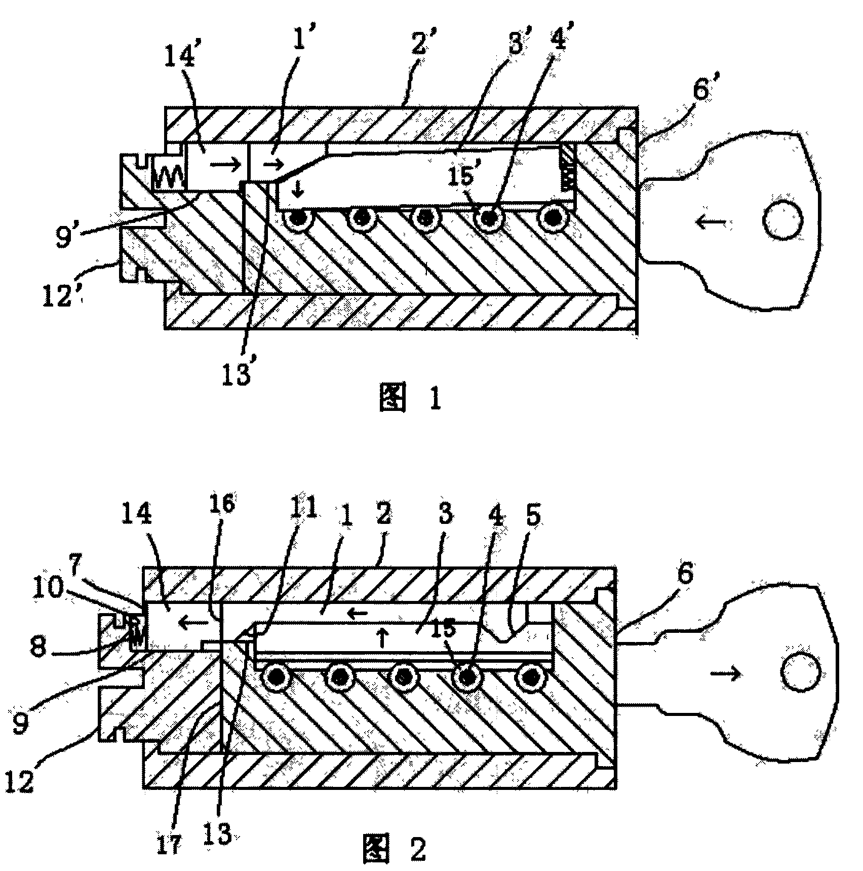
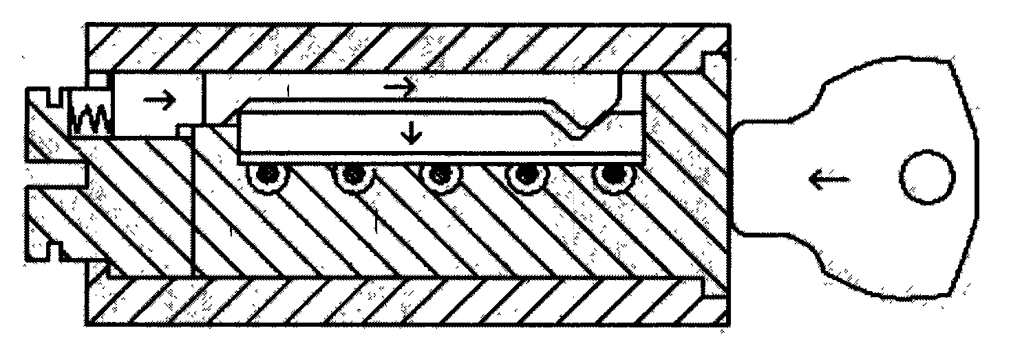
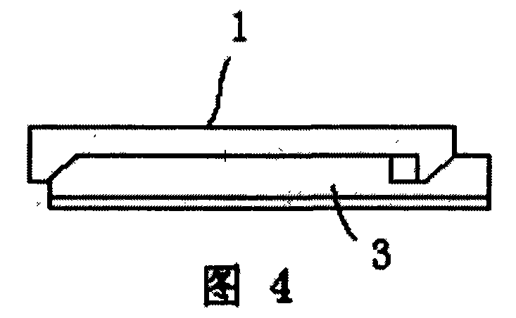
[0013] See Fig. 2, the lock core clutch structure of the present invention comprises the front lock core 6 and the rear lock core 12 in the lock body 2, and the locking edge column groove on the front lock core 6 is provided with a V-shaped The locking side column 3 matched with the groove 15 is provided with a slider chute 13 communicating with the locking side column groove on the front lock cylinder 6, and a lock pin is arranged on the rear lock cylinder 12 corresponding to the slider chute 13 of the front lock cylinder Chute 9, lock pin chute 9 has an end wall 10 at the afterbody of rear lock core, lock pin 14 is placed in the lock pin chute 9, and lock is set between the end wall 10 in the lock pin chute 9 and the lock pin 14. The pin return spring 8 is arranged radially along the lock core with a sliding block 1 matched with the locking side post 3, and two contact parts are arranged between the sliding block 1 and the locking side post 3 along the axial direction of the ...


PUM


Abstract

The present invention discloses a lock core clutch structure with a lock core capable of idling, comprising a front lock core and a back lock core inside a lock body, wherein a locking side column which can be matched with a groove on a lock core marble is arranged in a locking side column groove on the front lock core; a slider sliding chute communicated with the locking side column groove is arranged on the front lock core; a lock pin is arranged in a lock pin sliding chute corresponding to the slider sliding chute of the front lock core. The lock core clutch structure is characterized in that: a slider matched with the locking side column is arranged along the radial direction of the lock core; at least two contact parts adopting inclined surfaces are arranged between the slider and the locking side column along the axial direction of the lock core; one end of the slider is positioned in the slider sliding chute and is in contact with the lock pin on the back lock core. The lock core clutch structure can ensure that the slider cannot move along the axial direction of the lock core to open a lock when the lock is opened with a non-matched key, so as to achieve the objective of reducing mutual opening rate.

Description

technical field [0001] The invention belongs to mechanical locks, and relates to a clutch structure of a lock core which can rotate idly. Background technique [0002] Chinese Patent No. ZL200710034226.3 discloses a lock cylinder clutch structure in which the tumbler lock cylinder can rotate idly, as shown in Figure 1, it includes a lock body 2', a front lock cylinder 6' inside the lock body 2' and a rear lock Core 12', the front lock core 6' is provided with a locking side column 3' that can be matched with the lock cylinder pin 4' groove 15', and a slider that communicates with the locking side column groove is set on the front lock core 6'. Slot 13', the lock pin 14' is placed in the lock pin chute 9' corresponding to the slider chute 13' on the rear lock cylinder 12', and the slider 1' is placed in the slider chute 13', and the slider 1' The inclined surface 11' is in contact with the locking side column 3', and the other end is in contact with the locking pin 14'. Thi...

Claims


Application Information

Patent Timeline
Patent Type & Authority Applications(China)
IPC IPC(8): E05B27/00E05B15/00
Inventor 雷先鸣
Owner 雷先鸣
Why Eureka
Try Eureka