
Display device colour luminance compensation method, device and system

A technology for display equipment and color brightness, which is applied in the field of image processing and can solve the problems of uneven color brightness and small brightness loss of display equipment.

Active Publication Date: 2010-02-03
GUANGDONG VTRON TECH CO LTD
View PDF0 Cites 67 Cited by
  • Summary
  • Abstract
  • Description
  • Claims
  • Application Information

AI Technical Summary

Problems solved by technology

[0003] In view of the problems existing in the above-mentioned prior art, the object of the present invention is to provide a display device color brightness compensation method, compensation device and compensation system, which can effectively improve the problem of uneven color brightness of the display device, and brightness loss Small

Method used


Image

  • Display device colour luminance compensation method, device and system
  • Display device colour luminance compensation method, device and system
  • Display device colour luminance compensation method, device and system

Examples


Embodiment Construction

[0031] The solution of the present invention will be described in detail below with several specific examples thereof.

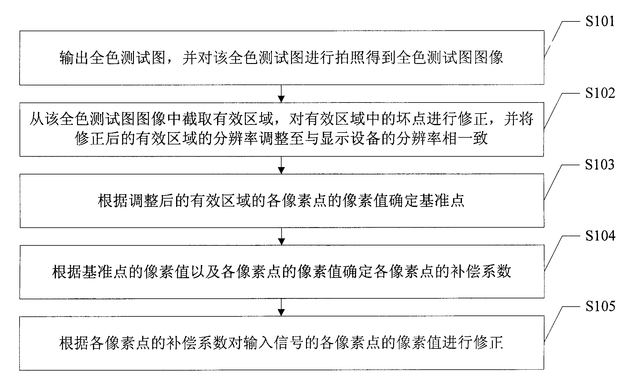
[0032] see figure 1 As shown, it is a schematic flow chart of Embodiment 1 of the color brightness compensation method for a display device of the present invention. As shown in the figure, the compensation method in this embodiment includes steps:

[0033] Step S101: Set the display device to an uncompensated state and output a full-color test chart, and take a picture of the full-color test chart to obtain a full-color test chart image, and enter step S102;

[0034] Step S102: intercepting the effective area from the full-color test image, correcting the dead pixels in the intercepted effective area, and adjusting the resolution of the corrected effective area to be consistent with the resolution of the display device, Enter step S103;

[0035] Step S103: Determine the reference point according to the pixel value of each pixel in the adjusted effective a...


PUM


Abstract

The invention relates to a display device colour luminance compensation method, device and system. The method includes that effective region is intercepted from a shot full colour test pattern image,dead pixels in the effective region are modified, the resolution ratio of the effective region after modification is adjusted to be consistent with that of the display device, a datum point is determined according to the pixel values of all pixel points of the effective region after adjustment, compensation coefficients of all pixel points are calculated according to the datum point and the pixelvalues of all pixel points, and the pixel values of all pixel points of an input signal are modified according to the compensation coefficient. As the pixel values of all pixel points of the full colour test pattern image are consistent under ideal condition, the compensation coefficient obtained according to the full colour test pattern image is more close to actual situation; and modification iscarried out according to the obtained compensation coefficient, thus the problem that the display device colour luminance is uneven can be solved, dark side and dark angle of the display device can be eliminated, and especially display effect can be greatly improved in the splice display field while luminance loss is low.

Description

technical field [0001] The invention relates to the technical field of image processing, in particular to a compensation method, a compensation device and a compensation system for compensating the color brightness of a display device. Background technique [0002] In the current technical field of large-size screen display, the technical methods adopted mainly include projection technology and flat panel display technology. The displayed image has the problem of uneven color brightness, and in the flat panel display technology, due to the uneven distribution of the background light source used, the displayed image will also have the problem of uneven color brightness. If it is only a single display, This kind of unevenness is not easy to be observed by the naked eye, but if it is applied to the splicing display, it will become very obvious, and there will be a very obvious problem of uneven color brightness around each splicing unit, thus Affects the display effect of the ...

Claims


Application Information

Patent Timeline
Patent Type & Authority Applications(China)
IPC IPC(8): G09G5/02G09G5/10
Inventor 刘文军许广
Owner GUANGDONG VTRON TECH CO LTD
Learn More