Vibrating rivet tool for pressing and fixing rivets in component holes and method for the use thereof

A technology for riveting tools and rivets, applied in the field of vibration riveting tools, to achieve the effect of simpler structure, reduced pressure and compact structure

Inactive Publication Date: 2010-02-03
AIRBUS OPERATIONS GMBH
View PDF4 Cites 2 Cited by
  • Summary
  • Abstract
  • Description
  • Claims
  • Application Information

AI Technical Summary

Problems solved by technology

The unit cannot perform conventional r

Method used


Image

  • Vibrating rivet tool for pressing and fixing rivets in component holes and method for the use thereof
  • Vibrating rivet tool for pressing and fixing rivets in component holes and method for the use thereof

Examples


Embodiment Construction

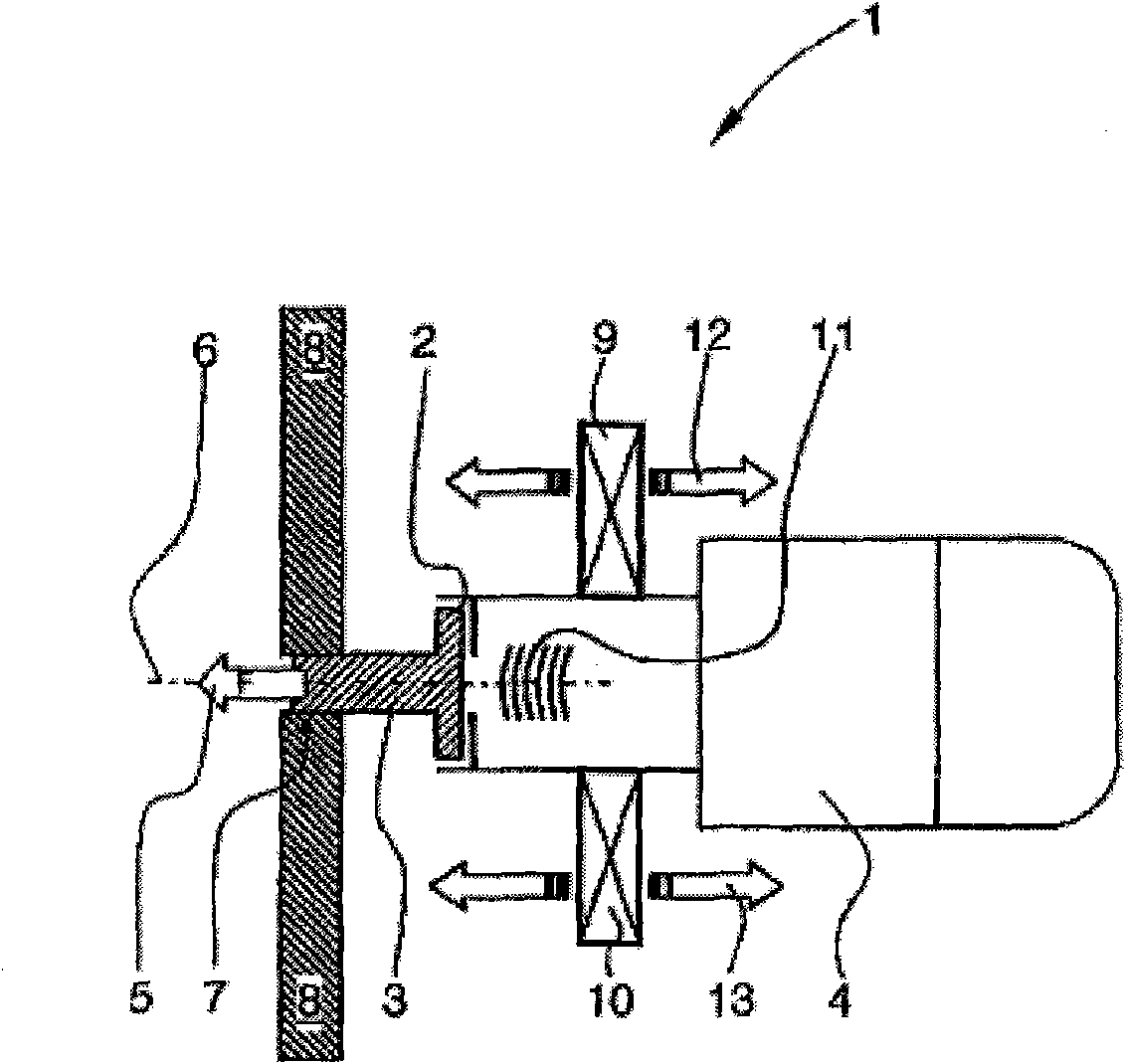
[0021] figure 1 A first variant of a vibratory riveting tool is shown.

[0022] Wherein, the vibration riveting tool 1 includes: a rivet container 2 for accommodating a rivet 3 and a driving unit 4 . The drive unit 4 generates a considerable purely mechanical static pressure 5 which acts substantially parallel to the longitudinal axis 6 of the rivet. In order to facilitate the process of pressing the rivet 3 into the component hole 7 in the component 8, vibration generators 9, 10 for generating mechanical vibrations 11 are arranged in the area of ​​the rivet container 2, the amplitude of which vibration is equal to the static pressure 5 overlay. exist figure 1 In the exemplary embodiment shown, the vibration generators 9 , 10 are arranged diametrically opposite one another in the region of the rivet container 2 . In principle, it is also possible to arrange the vibration generator 9 or the vibration generator 10 only on one side of the rivet container 2 . Furthermore, mor...


PUM


Abstract

The invention relates to a vibrating rivet tool (1, 15) for pressing and fixing rivets (3) in component holes (7) in component (8) of aircraft. The vibrating rivet tool (1, 15) comprises a rivet receptacle (2, 14) and a drive unit (4, 16) for producing a high static pressing force (5). According to the invention, the static pressing force (5) is superimposed by a mechanical vibration (11, 19), ofwhich the amplitude acts substantially in the direction of a longitudinal axis (6) of the rivet. As a result, the force necessary to press and fix the rivet (3) in a component hole (7) is reduced in such a way that the overall size and mass of the vibrating rivet tool (1, 15) according to the invention are smaller/ lower in comparison with conventional rivet tools. Due to the small overall size and low weight, the vibrating rivet tool (1, 15) can more easily be integrated in automated riveting processes.

Description

technical field [0001] The invention relates to a vibratory riveting tool for pressing and fastening rivets into component bores of components, in particular aircraft components, the vibratory riveting tool having a rivet container and a drive unit, the drive unit being positioned at the longitudinal axis of the rivet static pressure in the direction. Background technique [0002] Known embodiments of vibratory riveting tools and riveting hammers in aircraft construction use considerable mechanical force, especially acting in the axial direction of the rivet, to press the rivet into the rivet hole. In this case, the riveting tool must exert a force weighing up to one metric ton (approximately 10 kN). Due to the considerable force required to press rivets, riveting tools must be configured to be relatively large and heavy. Therefore, in the case of automated riveting for connecting components, riveting machines weighing up to one metric ton are required. [0003] More adva...

Claims


Application Information

Patent Timeline
IPC IPC(8): B21J15/12
CPCB21J15/12Y10T29/49943Y10T29/5377Y10T29/49956Y10T29/49954
Inventor 霍斯特·考特
Owner AIRBUS OPERATIONS GMBH
Why Eureka
Try Eureka